Impedance Compensation For A Differential Pair Of Conductive Paths

a technology of differential pair and conductive path, applied in the field of data processing, can solve problems such as signal quality degradation

Inactive Publication Date: 2013-04-18
IBM CORP
View PDF1 Cites 12 Cited by
  • Summary
  • Abstract
  • Description
  • Claims
  • Application Information

AI Technical Summary

Benefits of technology

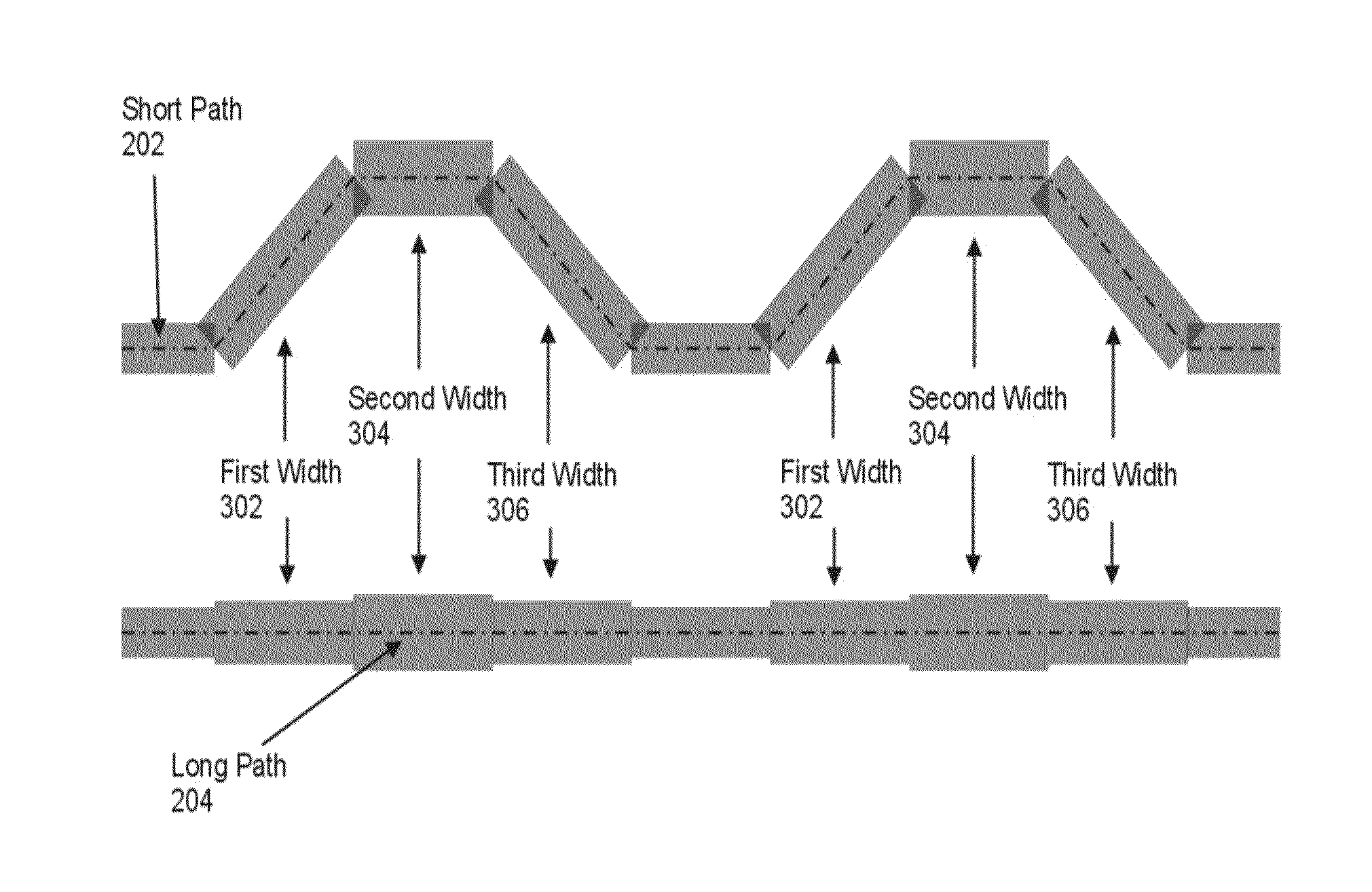
[0005]Methods, apparatus, and products for impedance compensation for a differential pair of conductive paths, including: determining the differential impedance for the differential pair of conductive paths, wherein each conductive path has a predetermined width; determining the geometry of one or more serpentine segments on one of the conductive paths in the differential pair; and determining, in dependence upon the differential impedance at each of the one or more serpentine segments, a serpentine segment path width at each of the one or more serpentine segments of the conductive paths in the differential pair. The methods, apparatus, and products described herein are useful in edge-coupled stripline and edge-coupled microstrip structures.
[0006]The foregoing and other objects, features and advantages of the invention will be apparent from the following more particular descriptions of exemplary embodiments of the invention as illustrated in the accompanying drawings wherein like reference numbers generally represent like parts of exemplary embodiments of the invention.

Problems solved by technology

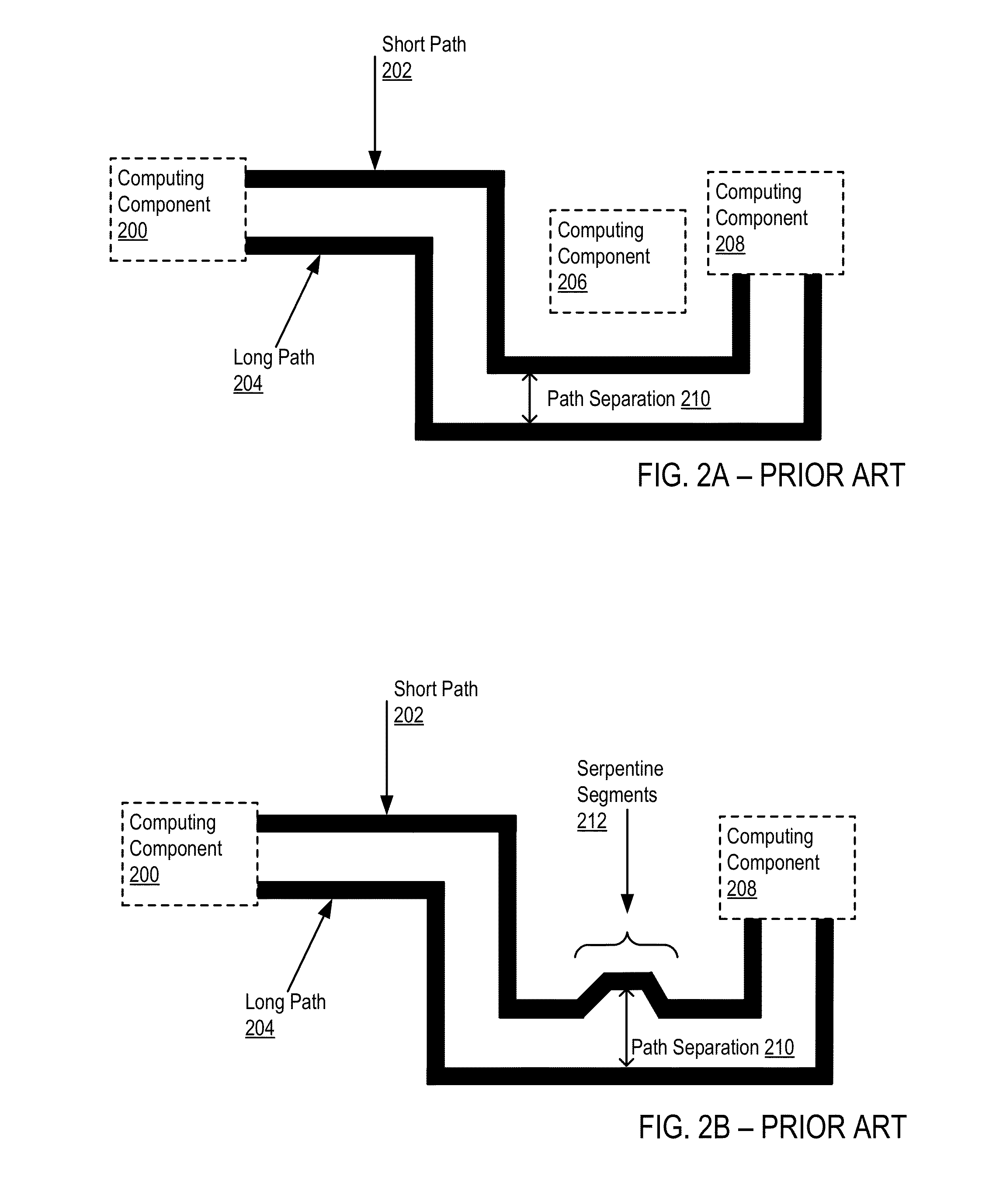
Because the separation of the conductive paths changes and the width of the conductive path does not change, the differential impedance of the serpentined section does not match the differential impedance of the remaining segments of the conductive paths, giving rise to reflection and a degradation of signal quality.

Method used


Image

  • Impedance Compensation For A Differential Pair Of Conductive Paths
  • Impedance Compensation For A Differential Pair Of Conductive Paths
  • Impedance Compensation For A Differential Pair Of Conductive Paths

Examples


Embodiment Construction

[0013]Example methods, apparatus, and products for impedance compensation for a differential pair of conductive paths in accordance with the present invention are described with reference to the accompanying drawings, beginning with FIG. 1.

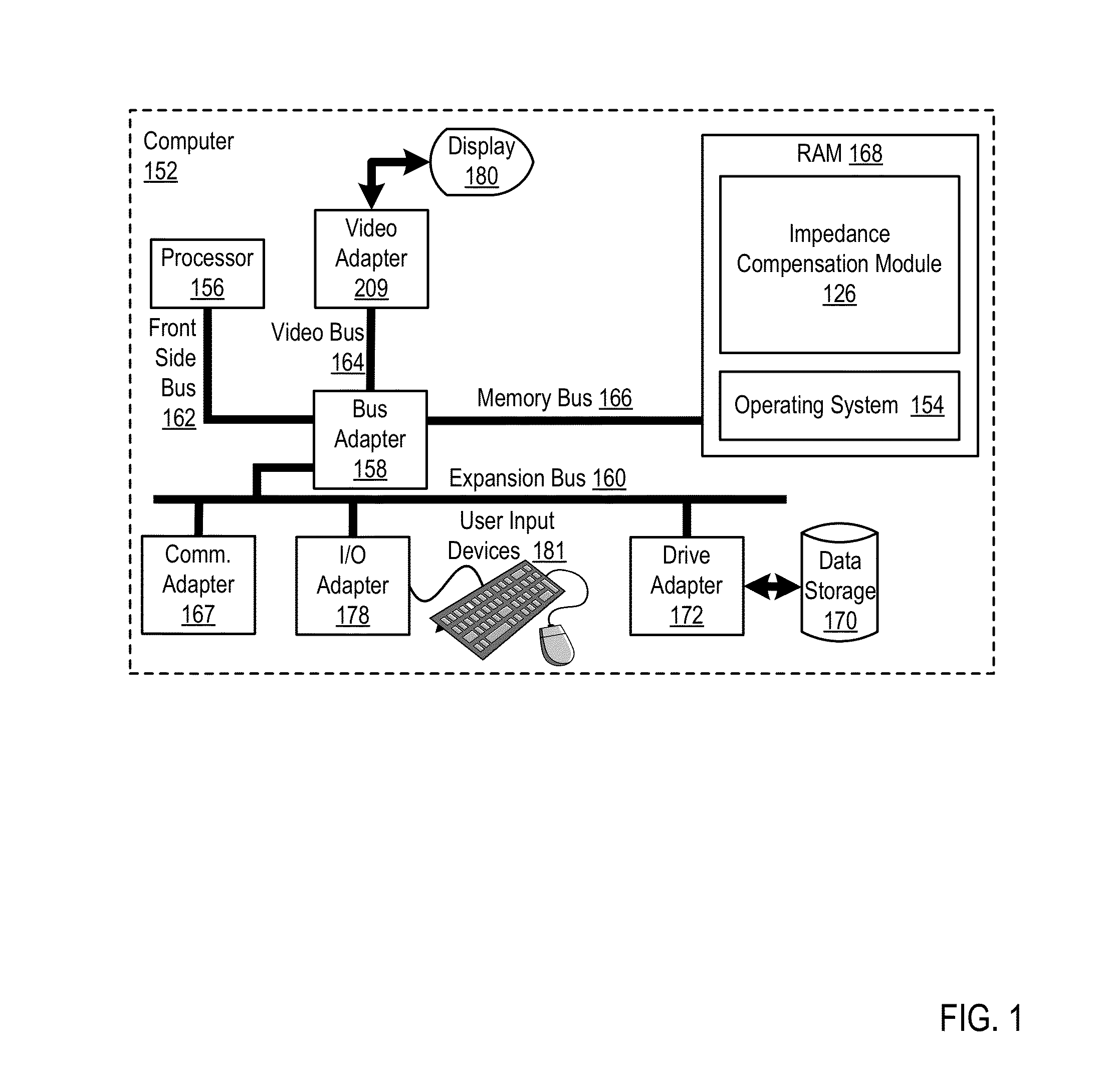
[0014]FIG. 1 sets forth a block diagram of automated computing machinery comprising an exemplary computer (152) useful in impedance compensation for a differential pair of conductive paths according to embodiments of the present invention. The computer (152) of FIG. 1 includes at least one computer processor (156) or ‘CPU’ as well as random access memory (168) (RAM') which is connected through a high speed memory bus (166) and bus adapter (158) to processor (156) and to other components of the computer (152).

[0015]Stored in RAM (168) is an impedance compensation module (126), a module of computer program instructions for impedance compensation for a differential pair of conductive paths according to embodiments of the present invention. The impeda...


PUM


Abstract

Methods, apparatus, and products for impedance compensation for a differential pair of conductive paths, including: determining the differential impedance and conductor geometry for the differential pair of conductive paths; determining the path length differential between the conductive paths in the differential pair of conductive paths; determining a centerline path to follow for a shorter conductive path in the differential pair of conductive paths, wherein the centerline path lengths the shorter conductive path such that the length of each conductive path in the differential pair of conductive paths is identical within a predetermined threshold; determining a number of subdivisions of one or more serpentine segments on one of the conductive paths in the differential pair; and determining, in dependence upon the differential impedance at each of the subdivisions of the one or more serpentine segments, a serpentine segment path width for the serpentine segment.

Description

BACKGROUND OF THE INVENTION[0001]1. Field of the Invention[0002]The field of the invention is data processing, or, more specifically, methods, apparatus, and products for impedance compensation for a differential pair of conductive paths.[0003]2. Description of Related Art[0004]In a differential pair of conductive paths, differential impedance is a function of line width and line spacing, among other things. High-speed differential pairs typically have a phase matching requirement, meaning that the lengths of the two conductive paths that comprise the differential pair must match within some tolerance. Frequently, differential pairs cannot follow a straight line across a printed circuit board (‘PCB’) from their source to their destination, and as such, the conductive paths of the differential pair must turn to avoid obstacles on the PCB. Each turn causes one of the conductive paths in the differential pair to lengthen with respect to the conductive path. The aggregate length mismatc...

Claims


Application Information

Patent Timeline
Patent Type & Authority Applications(United States)
IPC IPC(8): G06F17/50
CPCG06F17/5036G06F2217/82G06F17/5081G06F17/5077G06F30/394G06F2119/10G06F30/398G06F30/367
Inventor BYRNE, WILLIAM T.CHRISTOPHER, ROBERT J.KANGAS, PAUL D.PATEL, PRAVIN S.RANCK, DANIEL M.
Owner IBM CORP
Why Eureka
Try Eureka