Fluid delivery systems for climate controlled seats

a technology of climate control and flue gas, which is applied in the field of climate control, can solve the problems of one or more vehicle seats becoming hot and generally uncomfortable for the occupant, seat occupant's back and other pressure points may remain uncomfortably hot and/or sweaty, and problems that have been experienced with existing climate control systems, and achieve the effect of enhancing the comfort of a seated occupan

Inactive Publication Date: 2013-04-25
GENTHERM INC
View PDF0 Cites 133 Cited by
  • Summary
  • Abstract
  • Description
  • Claims
  • Application Information

AI Technical Summary

Benefits of technology

[0009]In some embodiments, the recessed area is configured to further receive a scrim which includes at least one opening through which fluids may pass. In one arrangement, the scrim comprises a plurality of openings. In other embodiments, the scrim comprises a single opening having an area generally greater than one-half of the total area of the scrim. In one embodiment, the scrim comprises one or more padding layers configured to generally enhance the comfort to a seated occupant. In yet other arrangements, the recessed area includes a bottom surface and at least one side surface. In one embodiment, the recessed area includes at least one film layer to cover at least of the bottom surface and the side surfaces. In another embodiment, the film layer comprises an air permeability that is lower than an air permeability of the spacer.

Problems solved by technology

For example, a vehicle exposed to the summer weather (e.g., where the vehicle has been parked in an unshaded area for a long period of time) can cause one or more of the vehicle seats to become hot and generally uncomfortable for the occupant for some time after first entering and beginning to use the vehicle.
Furthermore, even with normal air-conditioning, the seat occupant's back and other pressure points may remain uncomfortably hot and / or sweaty.
There are, however, problems that have been experienced with existing climate control systems for seat assemblies.
For example, the distribution system can be difficult to install and / or require a large number of components that results in increased steps during assembly.
In addition, many of the existing control systems for seat assemblies include relatively thick profiles that tend to interfere with the manufacture of the assembly and / or decrease an occupant's comfort level.

Method used


Image

  • Fluid delivery systems for climate controlled seats
  • Fluid delivery systems for climate controlled seats
  • Fluid delivery systems for climate controlled seats

Examples


Embodiment Construction

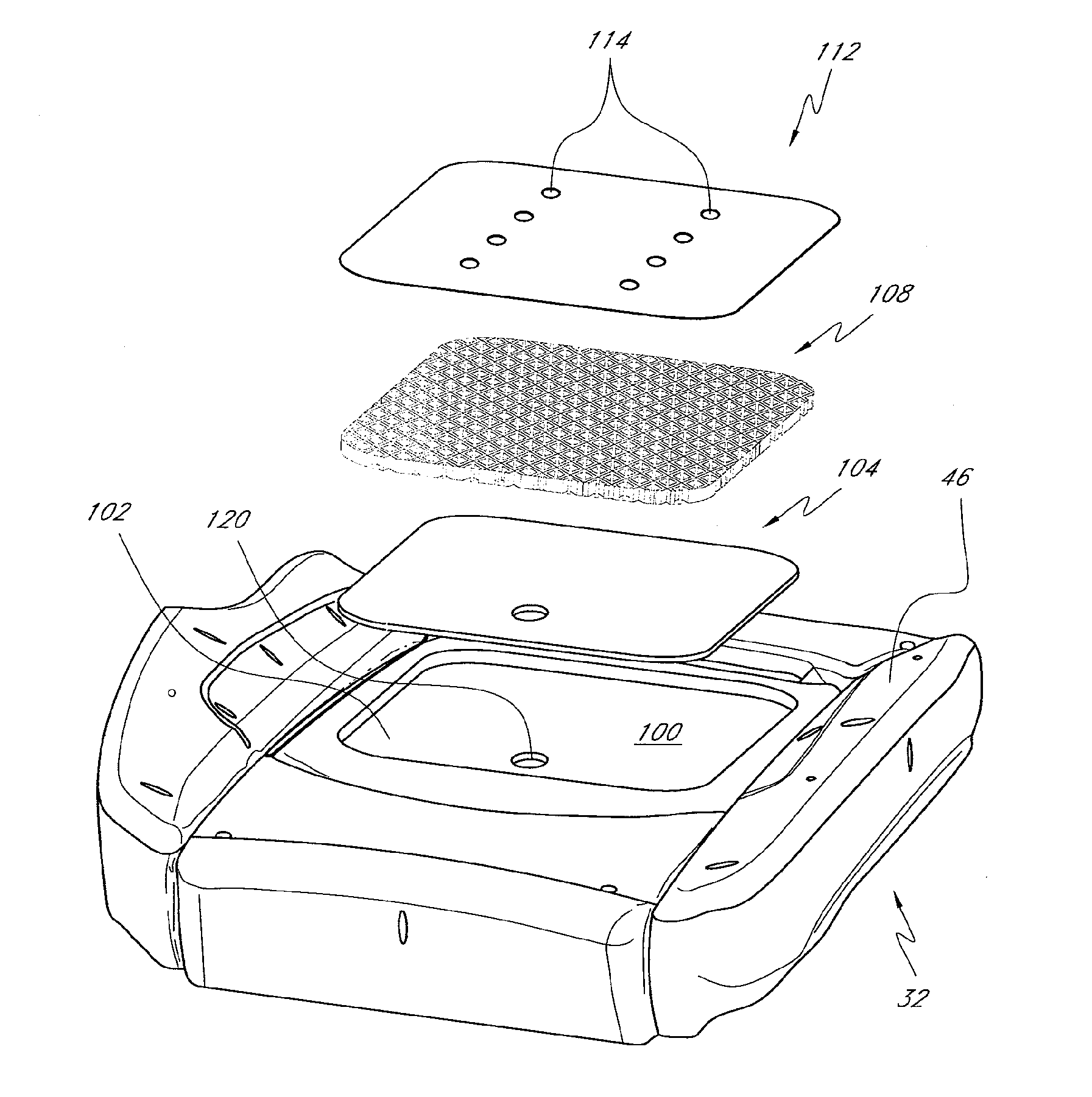
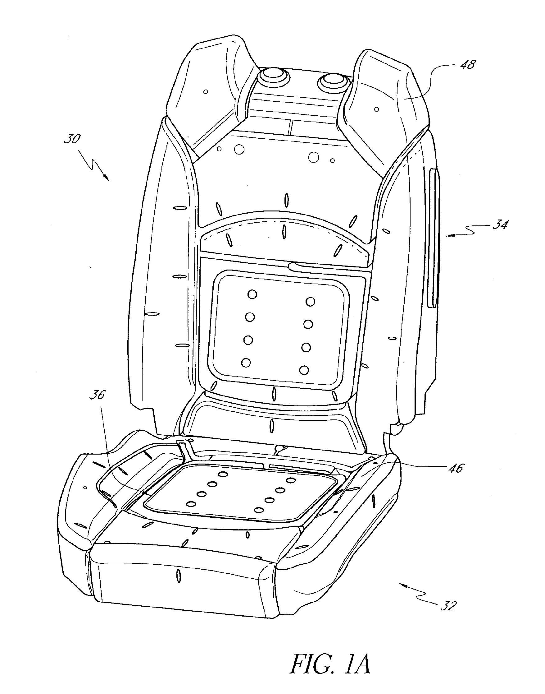
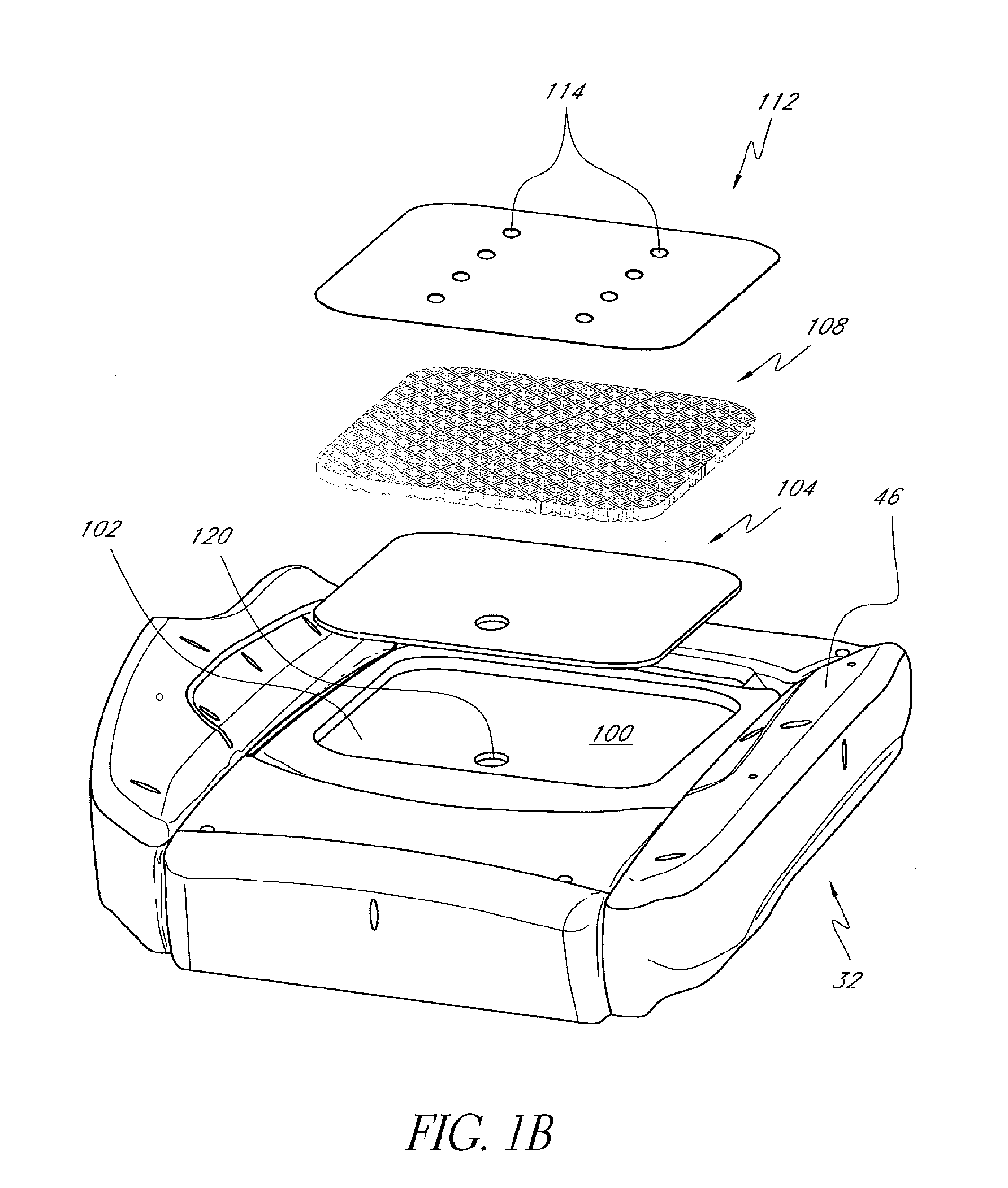
[0053]This application is generally directed to a climate control system for a seating assembly. The climate control system and the various systems and features associated with it are described in the context of an automotive seating assembly or other seat for a vehicle because they have particular utility in this context. However, the climate control system and the methods described herein, as well as their various systems and features, can be used in other contexts as well, such as, for example, but without limitation, trains, planes, motorcycles, buses, other vehicles, wheelchairs, sofas, task chairs, office chairs, other types of chairs, beds and / or the like. However, for convenience, the climate control system is described herein with specific reference to an automotive seat assembly.

[0054]In accordance with some embodiments, a seat portion or a backrest portion of seating assembly comprises a recessed area or wide groove region along its exterior surface. The recessed area can...


PUM


Abstract

A seat portion or a backrest portion of seating assembly comprises a recessed area or wide groove along its exterior surface. The recessed area can be configured to receive a spacer (e.g., spacer fabric, member, module, etc.) that helps maintains the spatial and structural integrity of the recessed area. In addition, a scrim layer can be positioned over the spacer fabric to help direct and / or distribute air or other fluid to an exterior surface of the seating assembly. The recessed area can also be configured to receive one or more films, occupant sensory devices, comfort layers, scrims, temperature sensors, heating devices and / or the like.

Description

CROSS-REFERENCE TO RELATED APPLICATIONS[0001]This application is a continuation application of U.S. patent application No. 12 / 167,190, filed Jul. 2, 2008, which claims the priority benefit under 35 U.S.C. §119(e) of U.S. Provisional Application No. 60 / 947,605, filed Jul. 2, 2007, the entireties of both of which are hereby incorporated by reference herein.BACKGROUND[0002]1. Field[0003]This application relates generally to climate control, and more specifically, to climate control of a seat assembly.[0004]2. Description of the Related Art[0005]Temperature modified air for environmental control of living or working space is typically provided to relatively extensive areas, such as entire buildings, selected offices, suites of offices or other rooms and / or the like. In the case of vehicles, such as automobiles, the entire vehicle is typically cooled or heated as a unit. There are many situations, however, in which more selective or restrictive air temperature modification is desirable. ...

Claims


Application Information

Patent Timeline
Patent Type & Authority Applications(United States)
IPC IPC(8): A47C7/74A47C21/04B60N2/56
CPCA47C7/74B60N2/5621B60N2/5685A47C7/748A47C21/048B60N2/5657
Inventor MARQUETTE, DAVIDTERECH, JOHN
Owner GENTHERM INC
Why Eureka
Try Eureka