Adjustable Gas Block

a gas block and adjustment technology, applied in the direction of weapons, weapon components, sighting devices, etc., can solve the problems of unsatisfactory characteristics, and achieve the effect of avoiding the use of silencers and being easily adjusted

Inactive Publication Date: 2013-04-25
REINKEN RALPH J
View PDF13 Cites 53 Cited by
  • Summary
  • Abstract
  • Description
  • Claims
  • Application Information

AI Technical Summary

Benefits of technology

[0011]The drum valve design has three inherent disadvantages. First is the very limited range of adjustment settings, typically two or three. These settings are usually comprised of fully closed, fully open, and one setting in between (typically engineered for a specific purpose). Second is the large surface areas of the mating parts (comprising the drum valve itself and the cylinder inside which it rotates). These surfaces are subject to buildup of carbon fouling from the propellant gas. After as few as 200 rounds have been fired, the valve can be rendered immovable without the use of large, and seldom field-available, tools. Third is the fixed-size orifices of the drum. These predetermined sizes are not adaptable to such field variables as: wear of the mating parts; wear of the rest of the firearm's operating system; the sometimes wide variation in working pressure of the ammunition in use; or other unforeseen field variables.
[0012]The prior art valve screw design, making use of a common socket head set screw to occlude the port between the barrel and the gas tube on M16/AR15/AR10/M4 type firearms, has two significant disadvantages. First is that nothing holds the screw in adjustment. An expedient remedy for this shortcoming is to apply a commercial thread-locking compound, such as Loctite, to the adjustment screw's threads. However, this action creates another problem: with the screw head locked in place, the extremely small hex wrench, used for adjustment, only serves to strip out the hex socket in the screw's head, thus rendering the screw removable only after extensive disassembly of the firearm. The second disadvantage of this design is that the adjustments are not precisely repeatable. A user may effectively adjust the valve for one set of circumstances, change it for another set of circumstances, bu

Problems solved by technology

Both are undesirable characteristics

Method used


Image

  • Adjustable Gas Block
  • Adjustable Gas Block
  • Adjustable Gas Block

Examples


Embodiment Construction

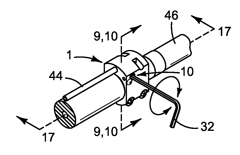
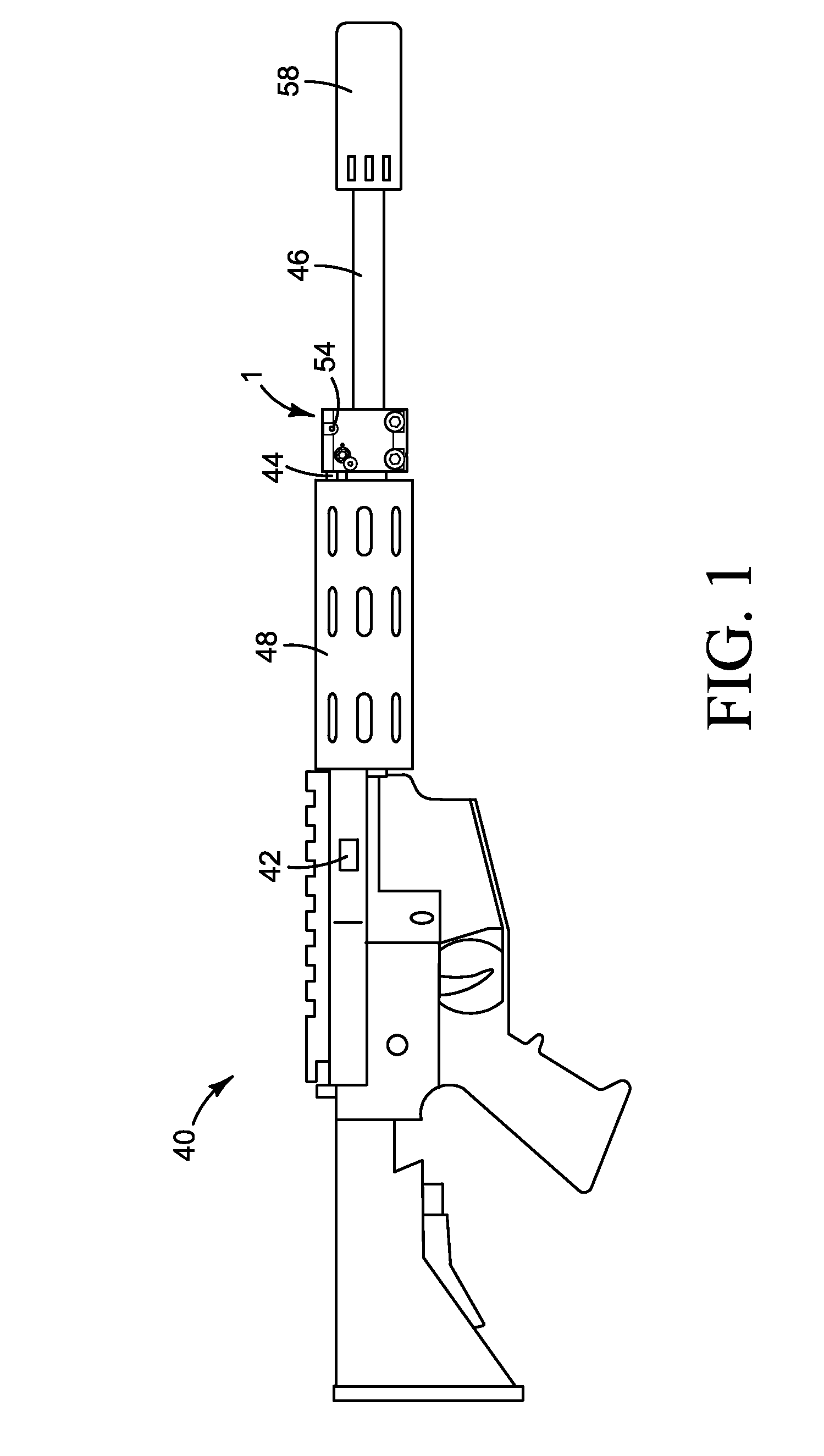
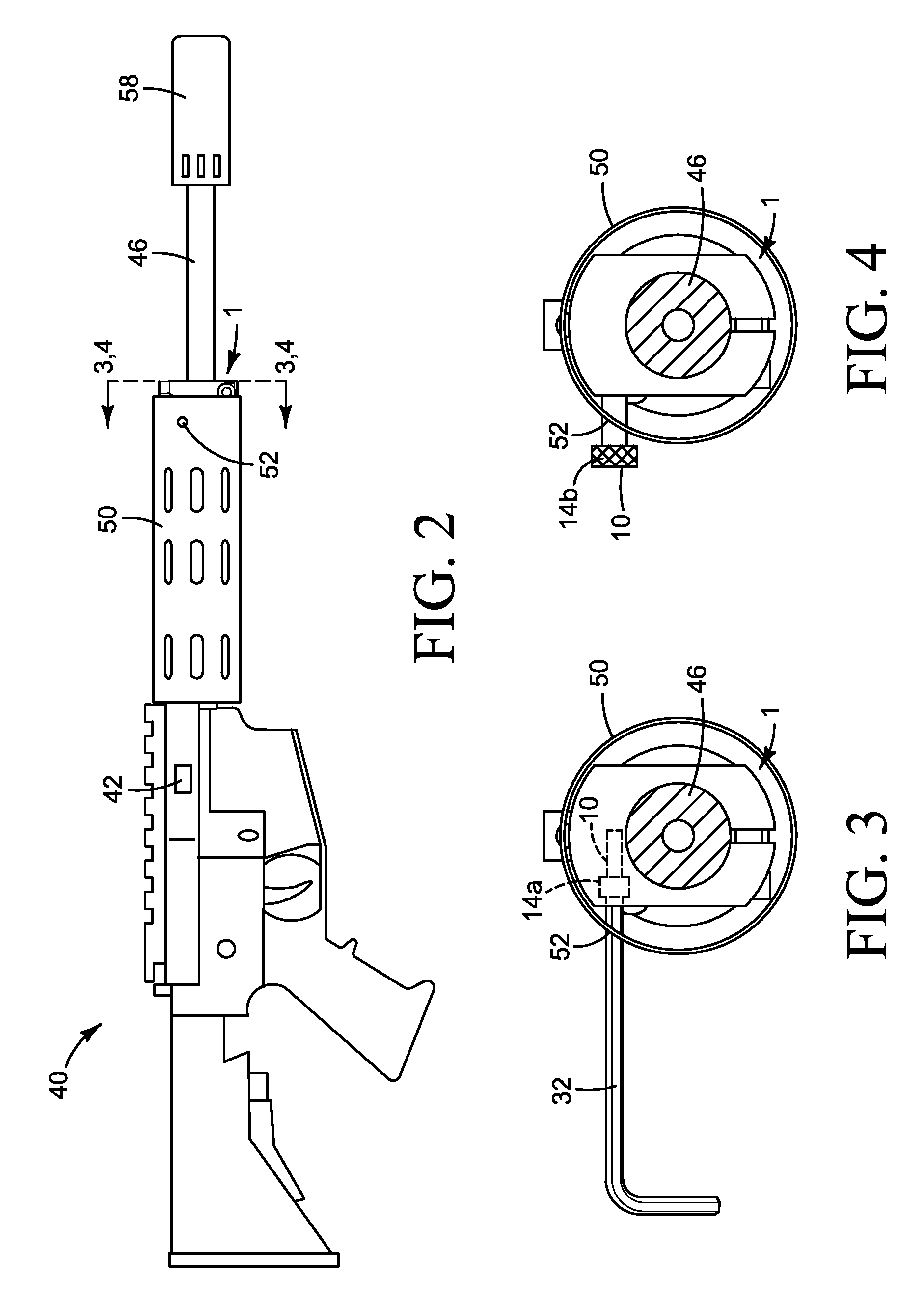
[0080]An auto-loading firearm's gas-operating system is one which utilizes a portion of the firearm cartridge's propellant gas as the energy source to operate the firearm's auto-loading mechanism. The illustrated embodiments of the invention are designed to provide users of gas-operated auto-loading firearms with a means of precisely and repeatably adjusting the amount of gas which is allowed to pass from the barrel of a host firearm into its gas-operating system, thus providing the ability to optimize the operation of a firearm by compensating for variations in ammunition loading, bullet weight, atmospheric temperature, cartridge caliber, and for the installation / removal of a silencer. The term “gas-operated auto-loading firearm” as used in this document includes, but is not limited to, direct impingement systems such as M16 / AR15 / AR10 / M4 type of firearms, as well as firearms that utilize a piston and cylinder in their gas-operating system. Please note that while the illustrated emb...


PUM


Abstract

An adjustable gas block designed to interface with the gas-operating system of an auto-loading firearm. This design provides continuously adjustable gas flow, from fully closed to fully open, in small, discrete, uniform, and fully-repeatable increments.
The design works by means of a click adjustment valve screw which has a number of grooves that are engaged by a spring-loaded detent. As the screw is turned in or out, either by a tool or by an integrated finger-adjustable knob or handle, the clicks of the detent provide both audible and tactile feedback to the user. This allows a user to optimize the operation of a firearm by responding to variations in ammunition loading, bullet weight, atmospheric temperature, cartridge caliber, and for the installation/removal of a silencer, each of which changes the volume and pressure characteristics of the gas-operating system.

Description

CROSS-REFERENCE TO RELATED APPLICATIONS[0001]This application claims the benefit of provisional patent application No. 61 / 550,569, filed 2011 Oct. 24 by the present inventor.FEDERALLY SPONSORED RESEARCH[0002]Not Applicable.SEQUENCE LISTING[0003]Not Applicable.BACKGROUND-FIELD OF INVENTION[0004]This invention relates to gas-operated auto-loading firearms, and specifically to user-adjustable gas blocks for such firearms.BACKGROUND-PRIOR ART[0005]A gas block for an auto-loading firearm is a device that is placed usually on the barrel of an auto-loading firearm, and used as a means to tap, collect, restrict, and direct the flow of propellant gas from the firearm's barrel into the auto-loading mechanism so as to provide the necessary energy to operate the auto-loading firearm. Adjustable gas blocks have been used on military auto-loading firearms for decades, as seen in such firearms as: the Soviet SVD; Yugoslavia's models 70, 76, and 95; the Belgian FAL; and recent Belgian SCAR rifles. ...

Claims


Application Information

Patent Timeline
IPC IPC(8): F41A5/28F41C27/00F41G1/02
CPCF41A5/28
Inventor REINKEN, RALPH J.
Owner REINKEN RALPH J
Why Eureka
Try Eureka