
Tire

a technology of tires and land portions, applied in the field of tires, can solve the problems of affecting driving stability, braking performance, and deterioration of stiffness of land portions, and achieve the effects of reducing the width of the groove, suppressing the deterioration of the stiffness of land portions, and improving the drainage performance of water entering the space between the road surface and the tread

Active Publication Date: 2013-04-25
BRIDGESTONE CORP
View PDF5 Cites 9 Cited by
  • Summary
  • Abstract
  • Description
  • Claims
  • Application Information

AI Technical Summary

Benefits of technology

The present invention provides a tire with a circumferential groove that has improved stiffness and drainage performance. The groove includes a wide and narrow groove portion that creates a pulsating water flow that improves drainage. The groove is recessed inwardly from the land portions to prevent stiffness issues and improve driving stability and braking performance. The groove also improves the braking performance and drive performance due to an increase in edge component in the tire's wear.

Problems solved by technology

However, the conventional tire described above have the following problem.
Since the groove walls of the land portions are recessed by the recessed portions, the stiffness of the land portions deteriorates.
There is a concern that this may negatively affect driving stability, a braking performance, and the like.

Method used


Image

  • Tire
  • Tire
  • Tire

Examples


first embodiment

(1) First Embodiment

[0026]A configuration of a pneumatic tire according to a first embodiment will be described below. Specifically, description will be given of (1.1) Configuration of Tread Pattern, (1.2) Detailed Configuration of Intra-groove Groove, and (1.3) Operations and Effects in this order.

[0027]In the first embodiment, a pneumatic tire 1 is a general radial tire including bead portions, a carcass layer, a belt layer, and a tread portion (not illustrated). Moreover, the pneumatic tire 1 may be filled with an inert gas such as a nitrogen gas instead of air.

(1.1) Configuration of Tread Pattern

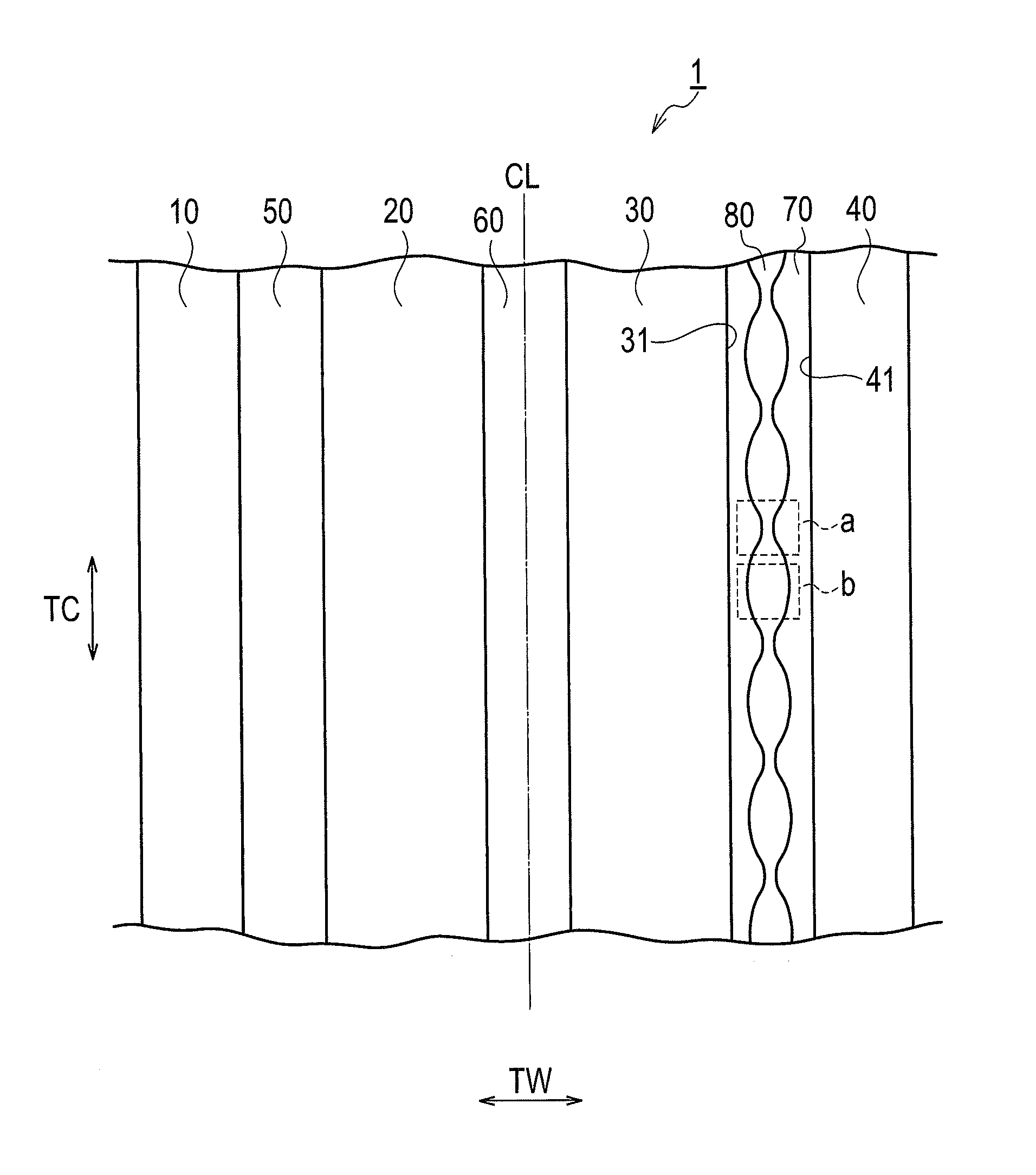
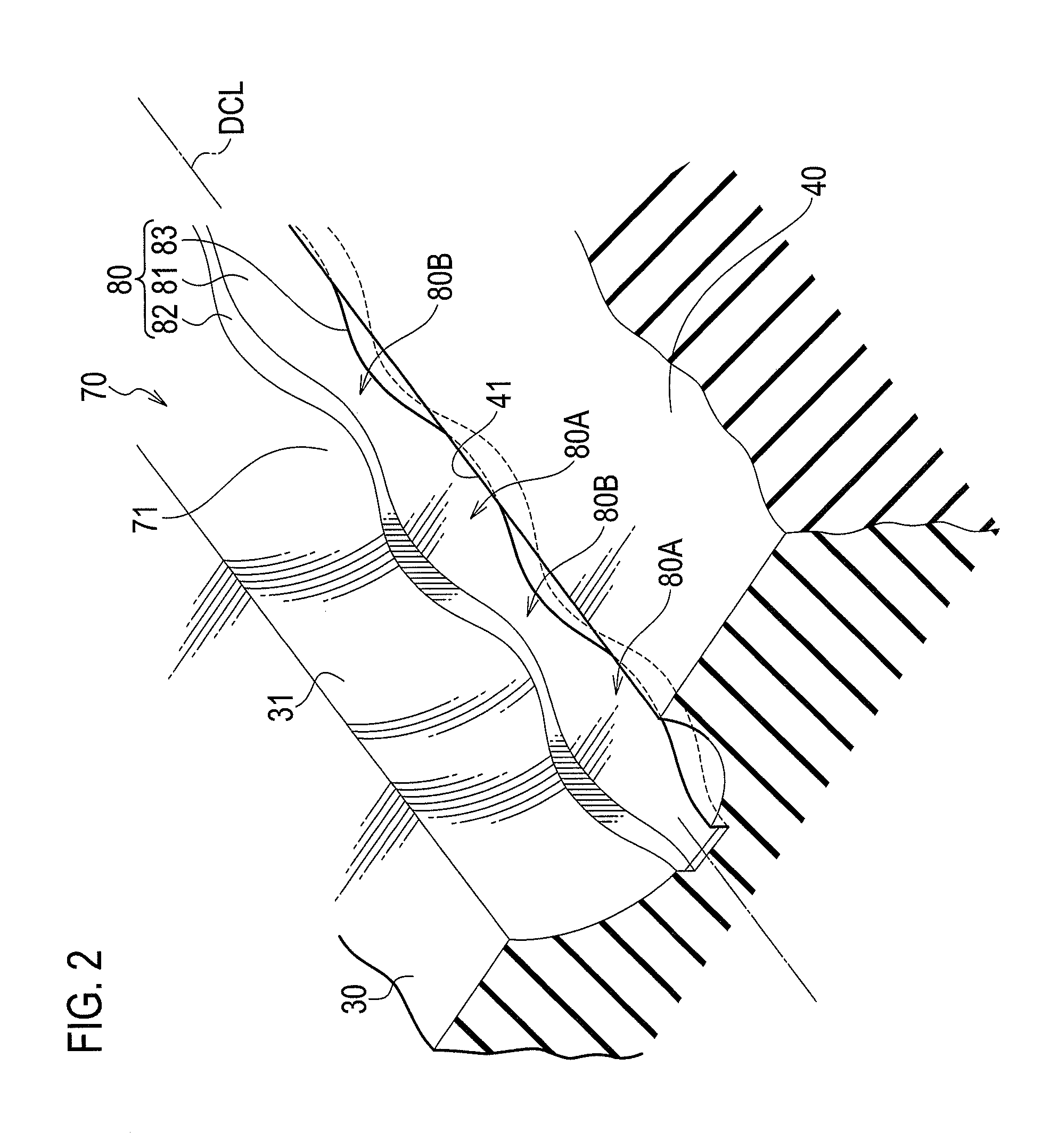
[0028]First, a configuration of a tread pattern of the pneumatic tire 1 according to the first embodiment will be described with reference to the drawings. FIG. 1 is a developed view showing the tread pattern of the pneumatic tire 1 according to the first embodiment. FIG. 2 is a perspective view showing a circumferential groove 70 according to the first embodiment and its vicinity.

[0029]...

second embodiment

(2) Second Embodiment

[0056]A pneumatic tire 2 according to the second embodiment of the present invention will be described below with reference to the drawings. Note that parts identical to the parts of the pneumatic tire 1 of the first embodiment described above are denoted by the identical reference numerals and different parts are mainly described.

[0057]In the first embodiment described above, no raised portions to be described later are provided in the circumferential groove 70 of the pneumatic tire 1. Meanwhile, in the second embodiment, the raised portions to be described later are provided in a circumferential groove 70 of the pneumatic tire 2. Specifically, in the second embodiment, (2.1) Detailed Configuration of Intra-Groove Groove and (2.2) Operations and Effects will be described with reference to the drawings.

(2.1) Detailed Configuration of Intra-Groove Groove

[0058]FIG. 5 is a perspective view showing the circumferential groove 70 according to the second embodiment and...


PUM


Abstract

A pneumatic tire 1 which includes a plurality of rib-shaped land portions extending in a tire-circumferential-direction and in which a circumferential groove is formed extending in the tire-circumferential-direction between the land portions. The circumferential groove is provided with an intra-groove groove formed to recess inwardly in a tire-radial-direction from the circumferential groove while having its upper ends at a groove bottom of the circumferential groove. Paired inner wall surface and outer wall surface forming the intra-groove groove each continuously extend in tire-circumferential-direction while meandering in tread-width-direction. The intra-groove groove includes a wide groove portion in which a groove width of the intra-groove groove in tread-width-direction is a predetermined width; and a narrow groove portion which is continuous with the wide groove portion and which has a narrower width than the predetermined width. The wide groove portion and the narrow groove portion are alternately provided in tire-circumferential-direction.

Description

TECHNICAL FIELD[0001]The present invention relates to a tire which includes multiple rib-shaped land portions extending in a tire circumferential direction and in which a circumferential groove extending in the tire circumferential direction is formed between the land portions.BACKGROUND ART[0002]Conventionally, as pneumatic tires (tires, hereafter) to be fitted to a passenger car and the like, there has been known a tire in which groove walls of land portions formed by circumferential grooves extending in a tire circumferential direction are provided with recessed portions formed in a tread width direction to improve a drainage performance of water entering the circumferential grooves (Patent Document 1, for example).[0003]Specifically, the recessed portions are provided at predetermined intervals in the tire circumferential direction and groove walls of the recessed portions are formed in half-moon shapes in a tread surface view. In this tire, water flowing in the circumferential ...

Claims


Application Information

Patent Timeline
Patent Type & Authority Applications(United States)
IPC IPC(8): B60C11/04
CPCB60C11/042B60C11/13B60C11/047B60C11/1353B60C2011/133B60C2011/1361B60C11/04B60C2011/1338
Inventor KATO, KEIICHI
Owner BRIDGESTONE CORP
Learn More