Component assembly jig

a component assembly and jig technology, applied in the direction of metal working equipment, work holders, metal-working equipment, etc., can solve the problems of poor yield and inability to easily distinguish, and achieve the effect of reducing the width of the insertion groove of the corresponding component and facilitating operation

Active Publication Date: 2017-01-26
TOPY FASTENER INDS
View PDF2 Cites 0 Cited by
  • Summary
  • Abstract
  • Description
  • Claims
  • Application Information

AI Technical Summary

Benefits of technology

[0031]In the case of thin plate-shaped components, the groove width of the corresponding component insertion grooves is also reduced. Guiding the ends of thin plate-shaped components along the component insertion guide facilitates the operation for inserting the plate-shaped components into the thin component insertion grooves.

Problems solved by technology

In this case, it is impossible to easily distinguish whether the sequence, orientation, and number of superposed components is correct after the plate-shaped components are superposed, and the yield is typically poor.

Method used


Image

  • Component assembly jig
  • Component assembly jig
  • Component assembly jig

Examples


Embodiment Construction

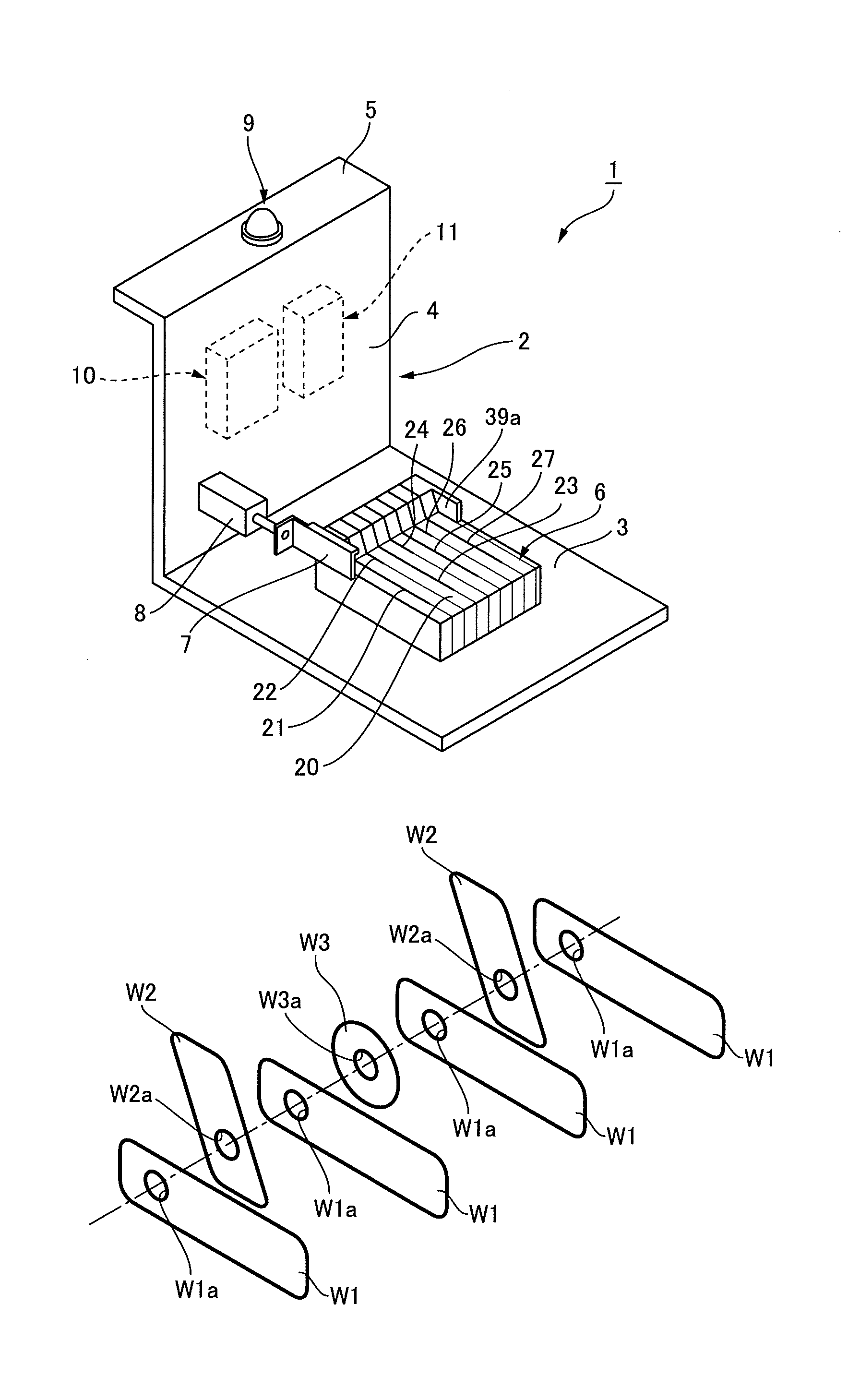
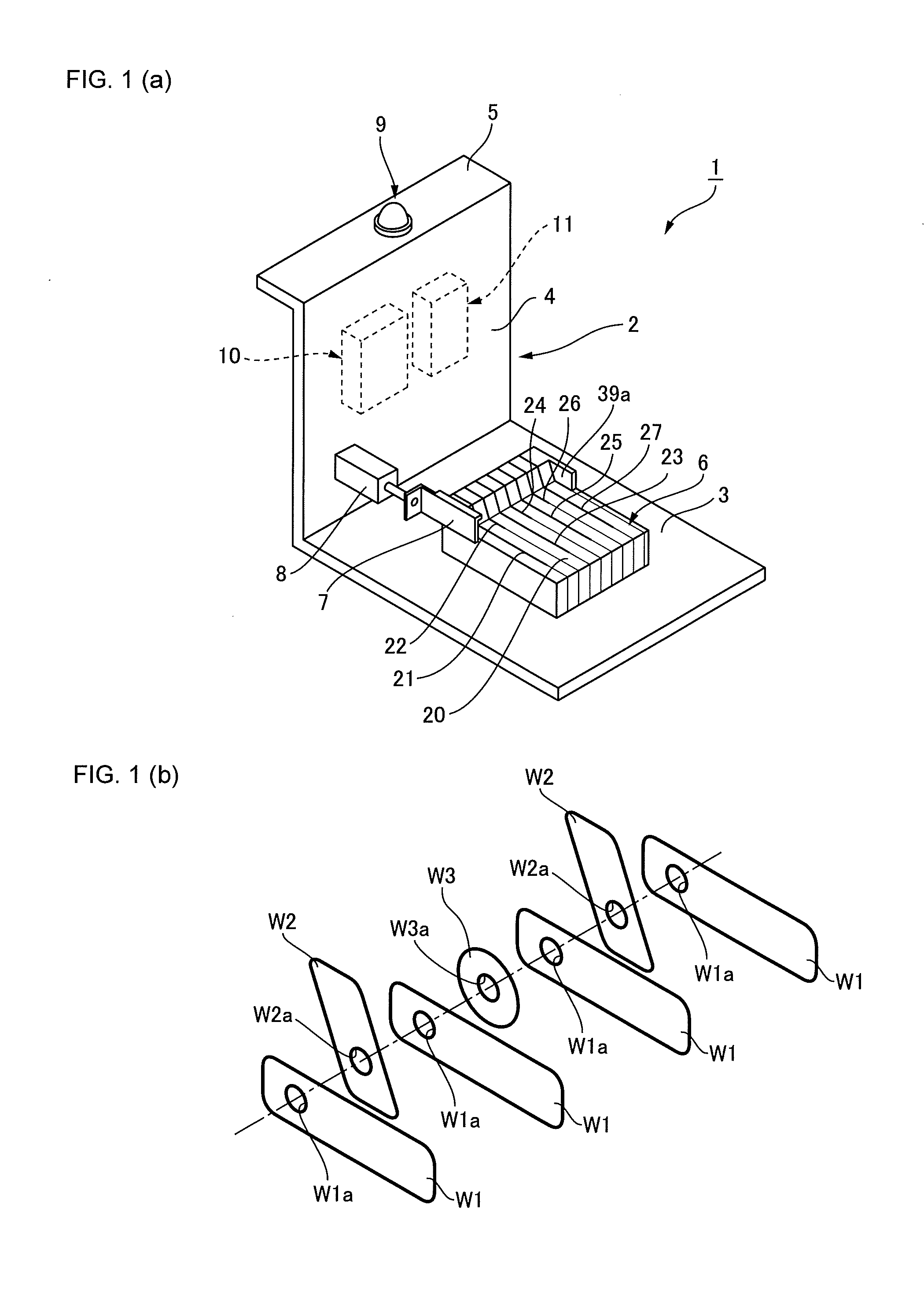
[0038]An embodiment of a component assembly jig to which the present invention is applied is described below with reference to the drawings. FIG. 1(a) is a schematic view of the overall configuration of a component assembly jig according to the present embodiment, and FIG. 1(b) is a schematic view of plate-shaped components to be assembled using the component assembly jig. The component assembly jig 1 can be used while placed on a work table or the like, and is used in order to superpose a plurality of plate-shaped components that include differently shaped plate-shaped components in a prescribed sequence and in a prescribed orientation and produce a single component assembly. For example, as shown in FIG. 1(b), the plate-shaped components include three types of differently shaped plate-shaped components W1, W2, W3, there being four plate-shaped components W1, two plate-shaped components W2, and one plate-shaped component W3, for a total of seven plate-shaped components; these plate...


PUM

PropertyMeasurementUnit
timeaaaaaaaaaa
thicknessaaaaaaaaaa
pressureaaaaaaaaaa

Abstract

When plate-shaped components are inserted in the correct order and orientation into component insertion grooves of a component assembly jig, the component insertion grooves are blocked by the plate-shaped components, and the blowing of compressed air is stopped. When the blowing of compressed air from the component insertion grooves is stopped, the pressure in a compressed-air path increases, and an alignment-complete lamp is illuminated. Using the component assembly jig enables an assembly operation for overlapping the plurality of plate-shaped components in the correct order and orientation, without excess or deficiency, to be efficiently performed without error.

Description

TECHNICAL FIELD[0001]The present invention relates to a component assembly jig for use in an assembly operation in which a plurality of plate-shaped components that include differently shaped plate-shaped components are overlapped, up to a prescribed number of plate-shaped components, along the thickness direction of the plate-shaped components in a prescribed sequence and in a prescribed orientation.BACKGROUND ART[0002]In various industrial products, etc., there are cases when a plurality of differently shaped plate-shaped components are overlapped and tightly secured by manual operations, and a single component assembly is assembled. In such operations, when a prescribed number of the same plate-shaped components are to be overlapped, care is needed to prevent any excess or deficiency in the number of plate-shaped components. If excess or deficiency in the number of plate-shaped components is the only concern, it is easy to determine whether there is an excess or deficiency visual...

Claims


Application Information

Patent Timeline
Patent Type & Authority Applications(United States)
IPC IPC(8): B23P19/10B23P19/04
CPCB23P19/04B23P19/10H01L21/67265H01L21/68Y10T29/49895Y10T29/49901Y10T29/49998Y10T29/53061Y10T29/53091Y10T29/53265B23P19/12B23P19/105B25B11/02
Inventor AKAHANE, YUJIAOYAMA, MAKOTO
Owner TOPY FASTENER INDS
Why Eureka
Try Eureka