
T-slot cutter

a cutter and slot technology, applied in the field of tslot cutters, can solve the problems of large number of tools and complex tool control, and achieve the effects of easy adjustment of the width of the groove cut into the workpi

Active Publication Date: 2018-05-17
OSG
View PDF0 Cites 0 Cited by
  • Summary
  • Abstract
  • Description
  • Claims
  • Application Information

AI Technical Summary

Benefits of technology

The present invention provides a T-slot cutter that can easily adjust the width of the groove and the angle at which it is machined into a workpiece. The spacer, which is placed between the first insert and the second insert, helps to accurately control the thickness of the groove. This makes it simpler to create and modify the shape of the groove in the workpiece.

Problems solved by technology

As a result, the number of tools becomes large and, in addition to increased tool manufacturing costs, there is also a problem of complex tool control.

Method used


Image

  • T-slot cutter
  • T-slot cutter
  • T-slot cutter

Examples


Embodiment Construction

[0044]Hereinafter, an embodiment of the present invention will be explained with reference to the drawings. The present invention is not limited to any of the specific configurations of the embodiment explained below.

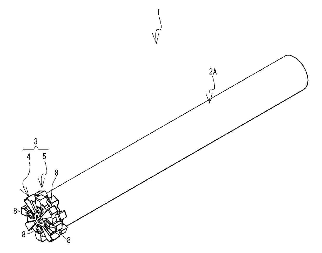
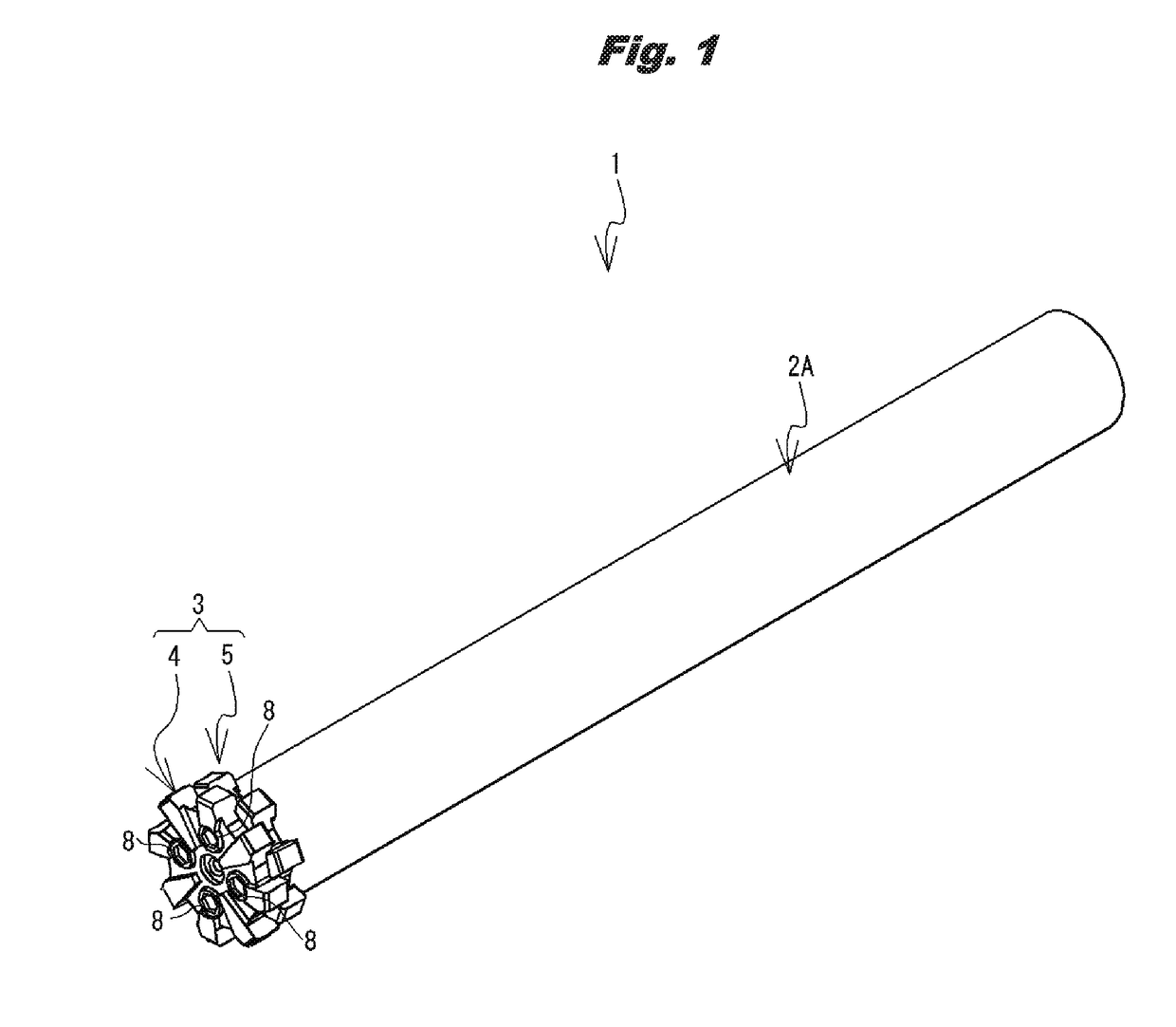
[0045]A structure of a T-slot cutter 1 will be explained with reference to FIG. 1 and FIG. 18. The T-slot cutter 1 shown in FIG. 1 is a tool (refer to FIG. 18) for cutting a T-shaped groove 501 (hereinafter referred to as a “T-groove”) into a workpiece 100, for example. The T-slot cutter 1 is an insert-type tool and includes a substantially cylindrical body 2A and an insert portion 3, which is detachably fixed to a leading end portion (one end portion in an axial direction) of the body 2A. The body 2A is a shank that can be attached to a main shaft or the like of a machine tool (not shown in the drawings) and can be rotationally driven. For example, carbon steel, alloyed steel, or the like, whose wear resistance, hardness, strength, etc. are lower than those of inserts ...


PUM


Abstract

A T-slot cutter (1) is a tool for cutting a T-groove in a workpiece, and includes a body (2A) and an insert portion (3). The insert portion (3) is fixed to a leading end portion of the body (2A) using screws (8). The insert portion (3) is configured by overlaying inserts (4) and (5). By changing a combination of the inserts configuring the insert portion (3), a groove width and an angular shape of the T-groove cut in the workpiece can be easily adjusted. On mating faces of the inserts (4, 5), convex portions and concave portions of the mating face of the insert (4) overlap with concave portions and convex portions of the mating face of the insert (5). As a result, the inserts (4, 5) partially overlap with each other in a thickness direction, and thus a protrusion length of the insert portion (3) can be shortened.

Description

TECHNICAL FIELD[0001]The present invention relates to a T-slot cutter that cuts a T-shaped groove into a workpiece.BACKGROUND ART[0002]A proposed T-slot cutter includes a handle and a blade provided on a leading end of the handle and cuts a T-shaped groove into a workpiece by being rotationally driven around an axis (see Patent Literature 1, for example).CITATION LISTPatent Literature[0003]Patent Literature 1: Japanese Laid-Open Patent Publication No. 2009-18354SUMMARY OF INVENTION[0004]With the T-slot cutter described in Patent Literature 1, it is necessary to make various preparations in accordance with a width (a length parallel to an axial direction) and an angular shape of a groove machined into a workpiece. As a result, the number of tools becomes large and, in addition to increased tool manufacturing costs, there is also a problem of complex tool control.[0005]It is an object of the present invention to provide a T-slot cutter that can easily adjust a groove width and an angu...

Claims


Application Information

Patent Timeline
Patent Type & Authority Applications(United States)
IPC IPC(8): B23C5/10B23C5/20B23C5/26
CPCB23C5/1072B23C5/202B23C5/26B23C2210/02B23C2200/361B23C5/1054B23C2210/03B23C2210/244B23C2270/14B23C2270/16B23C5/12B23C2210/242B23C2210/50
Inventor OSAWA, JIROYODA, TOMONORI
Owner OSG
Learn More