Pneumatic tire

a pneumatic tire and rib end technology, applied in the field of pneumatic tires, can solve the problems of uneven wear, nipping stone, and local wear at the rib end, and achieve the effects of reducing rigidity, improving wear resistance, and improving stone nipping resistan

Inactive Publication Date: 2008-05-29
TOYO TIRE & RUBBER CO LTD
View PDF2 Cites 28 Cited by
  • Summary
  • Abstract
  • Description
  • Claims
  • Application Information

AI Technical Summary

Benefits of technology

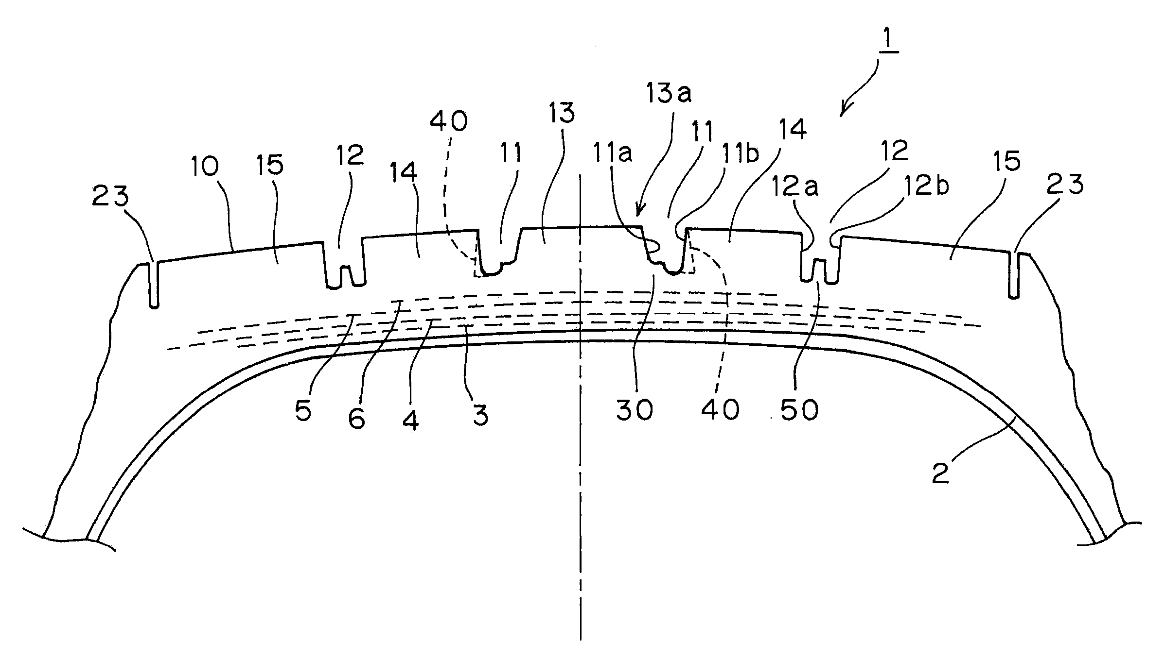
[0013]According to the pneumatic tire of the invention configured as described above, with the provision of the stepped-shaped raised area on at least on one of the groove walls of the main groove positioned at the center area of the tire (referred also to as the tire center side) in the circumferential direction, the rigidity of the ribs is secured without increasing the width of the ribs formed by the main grooves so that the 
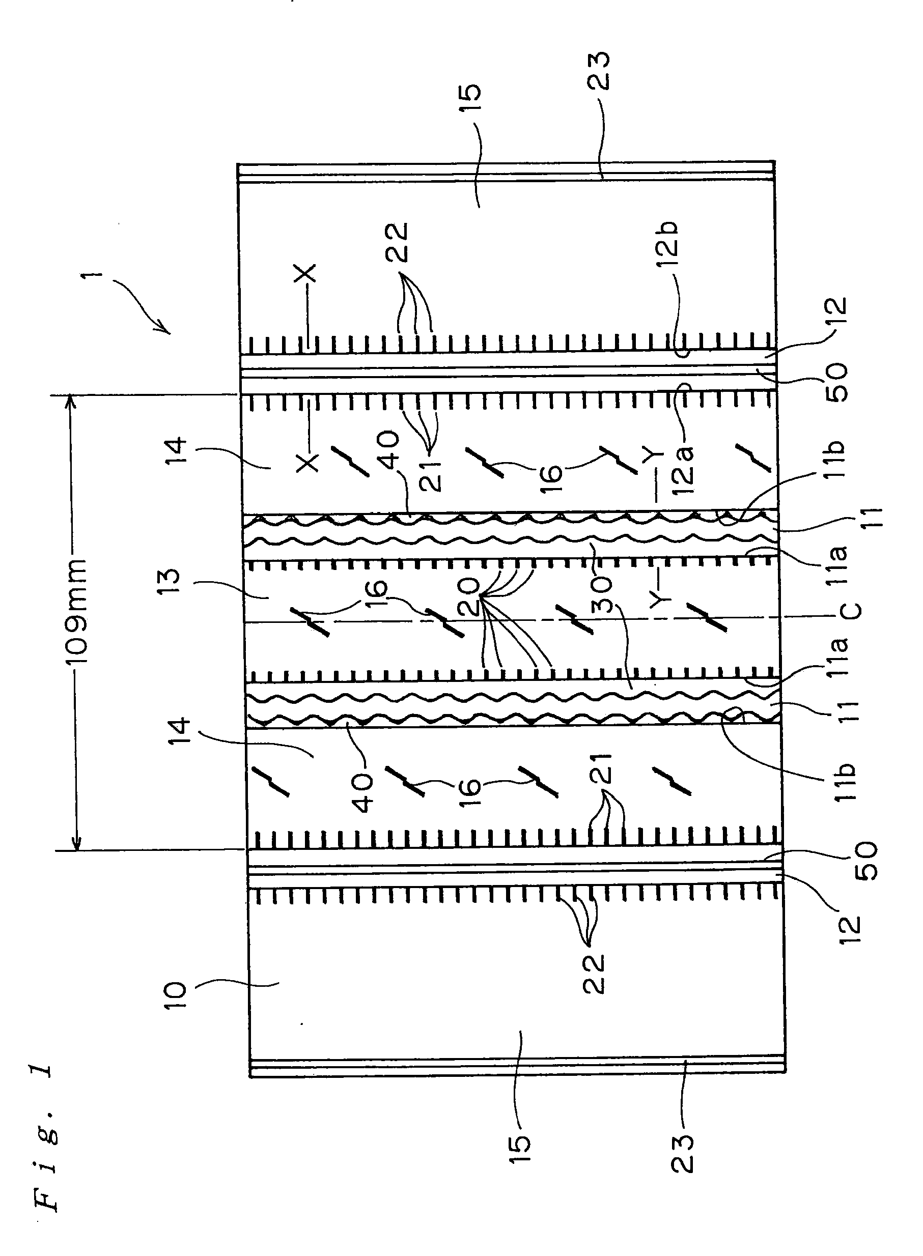
wear resistance is improved and stone-nipping is prevented by the raised portion, so that the stone-nipping resistance is improved. With the provision of the zigzag shape including the repetitive peaks and troughs circumferentially on the wall portion of the raised area, the proximal portion of the rib is removed, and hence the rigidity thereof is lowered relatively with respect to the rib surface, so that deformation of the groove wall on the surface side is restrained. In addition, the zigzag shape appears when having worn, and the braking property and the driving property may be secured on and after the medium phase of wear so that the control stability is maintained.
[0014]The main groove positioned on both outsides (referred also to as the shoulder sides) of the main groove positioned at the center area of the tire are each adapted in such a manner that when the thickness of rubber at the bottom portion of the main groove is thinner than that of the rib portion, and when the belt ply on the outermost layer is arranged inside the shoulder-side main grooves, the groove walls of the rib is deformed to bulge as if they are convoluted toward the center side with the groove bottoms as fulcrums and the tread surface is moved when it comes into contact with the ground. Therefore, by enhancing the rigidity of the groove bottom with the ridge provided at the center portion of the groove, the stress caused by the deformation can be absorbed. In contrast to the V-shaped main groove in the related art in which the angle of inclination of the groove walls exceeds 10°, the angles of inclinations of the groove walls of the main groove with respect to the normal lines of the tread surface at the portion where the main groove exists are set to be parallel to each other or to be 5° or smaller in the direction to reduce the width of the grooves of the main grooves on the radially inside of the tire, so that the ground contact pressure of the rib ends is lowered and hence deterioration of wear resistance due to the deformation is restrained. The normal line of the tread surface of the main groove portion represents the normal line with respect to the tangential line with respect to the ends of the main groove of a standard rim prescribed by the TRA (the Tire and Rim Association) with prescribed air pressure / no load state.
[0015]The ridge restrains the stone-nipping into the main groove, and restrains shear deformation of the groove wall of the rib on the grounded ends toward the center of the tire due to a lateral force applied thereto when a vehicle is turned. Therefore, the ridge is disposed independently from the groove walls on both sides so as not to impair the deformation of the rib ends.
[0016]With the provision of the zigzag notches formed into a triangular pyramid shape directed toward the groove bottom on one of the groove walls of the main groove positioned at the center area of the tire circumferentially of the tire at regular intervals, the rigidity of the proximal portion of the rib is reduced to cause the bulging of the groove wall surface on load to move toward the groove bottom and reduce the extent of movement of the rubber at the rib ends on the ground contact surface, that is, the widthwise movement at the rib ends, so that the uneven wear resistance is improved. In addition, the zigzag shape appears on the tread surface in association with the progress of wear, so that the braking property and driving property on the wet road are also secured.
[0017]Furthermore, with the arrangement of the peaks and the troughs of the wall portion of the raised area and of the triangular pyramid shapes at the same intervals in such a manner that the peaks and the troughs of them are arranged so as to oppose to each other in pairs with the intermediary of the main groove, the width of the groove bottom is secured and hence water drainage property is secured, and the radius of curvature (R) for joining the groove bottom and the groove wall continuously is set to be a relatively large value, so that generation of cracks on the groove bottom may be restrained.

Problems solved by technology

Uneven wear of a pneumatic tire having a rib pattern mainly includes step wear starting from grounded ends in the direction of axis of rotation of the tire and river wear generating at rib ends on both sides of a main groove, and there is a problem in the related art that particularly the river wear which is uneven wear occurring locally in the circumferential direction at the rib ends tends to occur.
On the other hand, the rib pattern has a problem that it tends to nip stones in the groove, and the nipped stone is firmly held in the groove and cannot come out easily.
Therefore, when the rib comes into contact with the ground, the rib is deformed by vertical force on load and groove walls are bulged toward the center of the groove, the groove walls tend to bulge on the side of the ground contact surface having a smaller width in comparison with the groove bottom, and hence the uneven wear can easily occur due to the movement of rubber.
Therefore, uneven wear tends to occur on the shoulder sides in comparison with the center side.
The rib pattern has the problem of the above-described stone-nipping, and also a problem in the braking property and the driving property on the wet road surface.
Therefore, even when the short sipes are provided as described above, there remains a problem of lowering of the braking property on the wet road on and after the medium phase of wear.

Method used


Image

  • Pneumatic tire
  • Pneumatic tire
  • Pneumatic tire

Examples


example

[0060]Referring now to an example, the invention will be described in detail.

[0061]A prototype tire having the tread pattern shown in FIG. 1 including the raised areas 30 in the pair of main grooves 11 on the center side, the triangular-pyramid-shaped notches 40, and the ridges 50 in the main grooves 12 on the both shoulder sides set as shown in the table shown below was manufactured and the performance of the tire was evaluated. The dimensions of the raised area or the like were as shown below. In the table, a letter G indicates that the value is set, and lateral bars indicate that the value is not set.

[0062]The main grooves 11 and 12 of the prototype tire both had a width on the tread surface of 11 mm, a depth of 12 mm. The height of the raised areas 30 was 4 mm, the width of the upper surface of the stepped portion was 3 mm, the depth from the pitches to the troughs of the zigzag wall portion was 1.8 mm, and the trough-to-trough pitches were 8 mm. The triangular-pyramid-shaped no...


PUM


Abstract

A pneumatic tire of the invention includes: a stepped-shaped raised area provided in the main groove positioned at a center area of the tire so as to be continued circumferentially of the tire, connected to either the main groove walls, and raised from the groove bottom; and a ridge lower than a tread surface of the tire in each of the main grooves on both outsides of the main groove at the center area of the tire so as to be raised from the center of the groove bottom continuously along the length thereof without being joined with the groove walls, and the angle of inclination of the main groove walls with respect to the normal line of the tangential line on the tread surface of the main groove portion is parallel to each other or is 5° or smaller.

Description

BACKGROUND OF THE INVENTION[0001]1. Field of the Invention[0002]The present invention relates to a pneumatic tire having a rib pattern including a plurality of land portions continuing substantially circumferentially of the tire and, more specifically, to a pneumatic tire having a rib pattern which improves wear resistance, improves stone-nipping resistance, prevents generation of cracks on the groove bottom, and secures braking property and driving property when having worn.[0003]2. Description of the Related Art[0004]Uneven wear of a pneumatic tire having a rib pattern mainly includes step wear starting from grounded ends in the direction of axis of rotation of the tire and river wear generating at rib ends on both sides of a main groove, and there is a problem in the related art that particularly the river wear which is uneven wear occurring locally in the circumferential direction at the rib ends tends to occur.[0005]An effective countermeasure for the step wear is to prevent th...

Claims


Application Information

Patent Timeline
Patent Type & Authority Applications(United States)
IPC IPC(8): B60C11/13
CPCB60C11/042B60C11/13B60C11/047Y10S152/01B60C11/045Y10S152/03Y10S152/901B60C2011/1254
Inventor OHARA, MASAAKI
Owner TOYO TIRE & RUBBER CO LTD
Why Eureka
Try Eureka