

Pneumatic tire
a technology of pneumatic tires and tires, applied in the field of pneumatic tires, can solve the problems of lowering the rigidity excessive falling of the land portion, and lowering the braking performance of the tire on the icy road surface, and achieve the effect of grooving
Active Publication Date: 2015-06-18
TOYO TIRE & RUBBER CO LTD
View PDF6 Cites 7 Cited by
- Summary
- Abstract
- Description
- Claims
- Application Information
AI Technical Summary
Benefits of technology
The patent describes a sipe (a type of slit) used in a tire tread design. The sipe has a specific shape and is designed to improve tire performance. The sipe has two large width portions, a neck portion, and a groove bottom. The groove width gradually decreases towards the opening end and increases towards the neck portion. The sipe is inclined to improve its performance. The technical effect of this design is improved tire performance, particularly in terms of tire tread design.
Problems solved by technology
However, when the number of sipes formed on the land portion is increased, the rigidity of the land portion is lowered so that the land portion falls excessively.
Accordingly, a ground contact area is decreased and, at the same time, a ground contact pressure is locally increased so that ice on an icy road surface is melted whereby a water membrane is liable to be formed thus giving rise to a drawback that a braking performance of a tire on an icy road surface is lowered.
Further, when the land portion falls excessively, the land portion is liable to be worn non-uniformly or the fallen land portion rubs a road surface when the fallen land portion returns to an original position after being separated from the road surface thus also giving rise to a drawback that an abnormal sound is liable to be generated.
Method used
View moreImage
Smart ImageViewing Examples

Examples
example 1
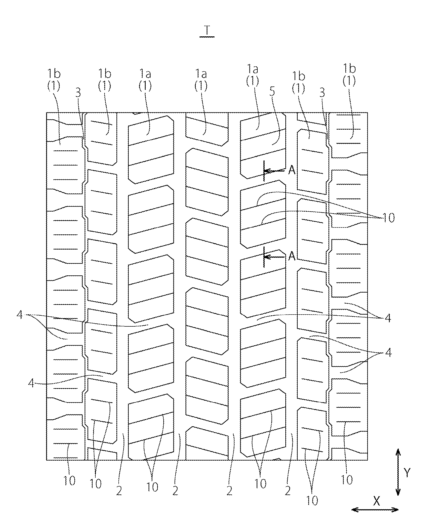
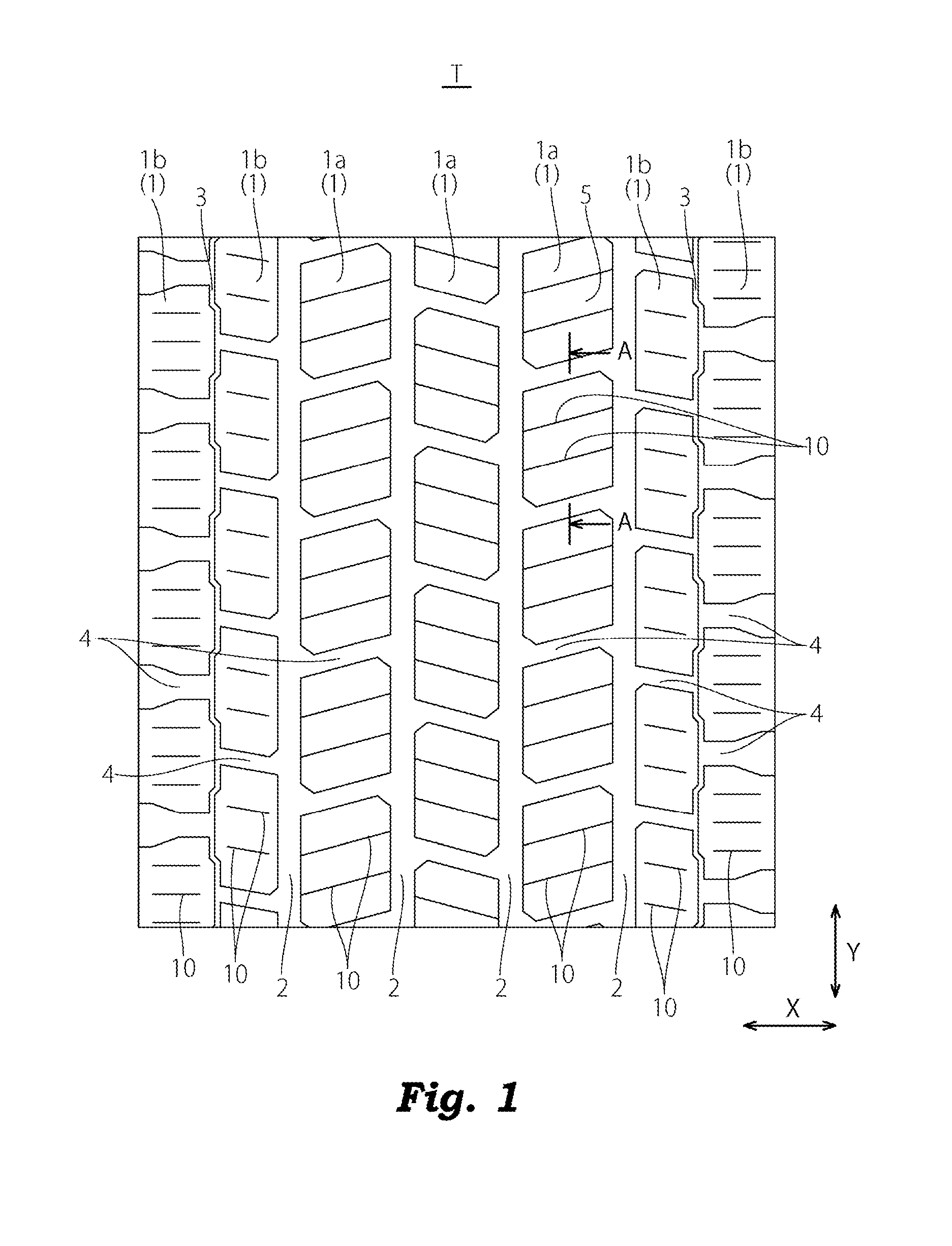
[0041]In the example 1, the sipe 10 having the cross-sectional shape shown in FIG. 2 was formed on all blocks in the tread pattern T shown in FIG. 1. The respective sizes such as the depth H of the sipe 10, the length H1 in the sipe depth direction D from the opening end 12 to the neck portion 16, the length H2 in the sipe depth direction D from the opening end 12 to the first large width portion 14, the width W1 of the opening end 12 of the sipe 10, the groove width W2 of the first large width portion 14, the groove width W3 of the neck portion 16, and the groove width W4 of the second large width portion 18 are shown in Table 1.
Login to View More PUM
 Abstract
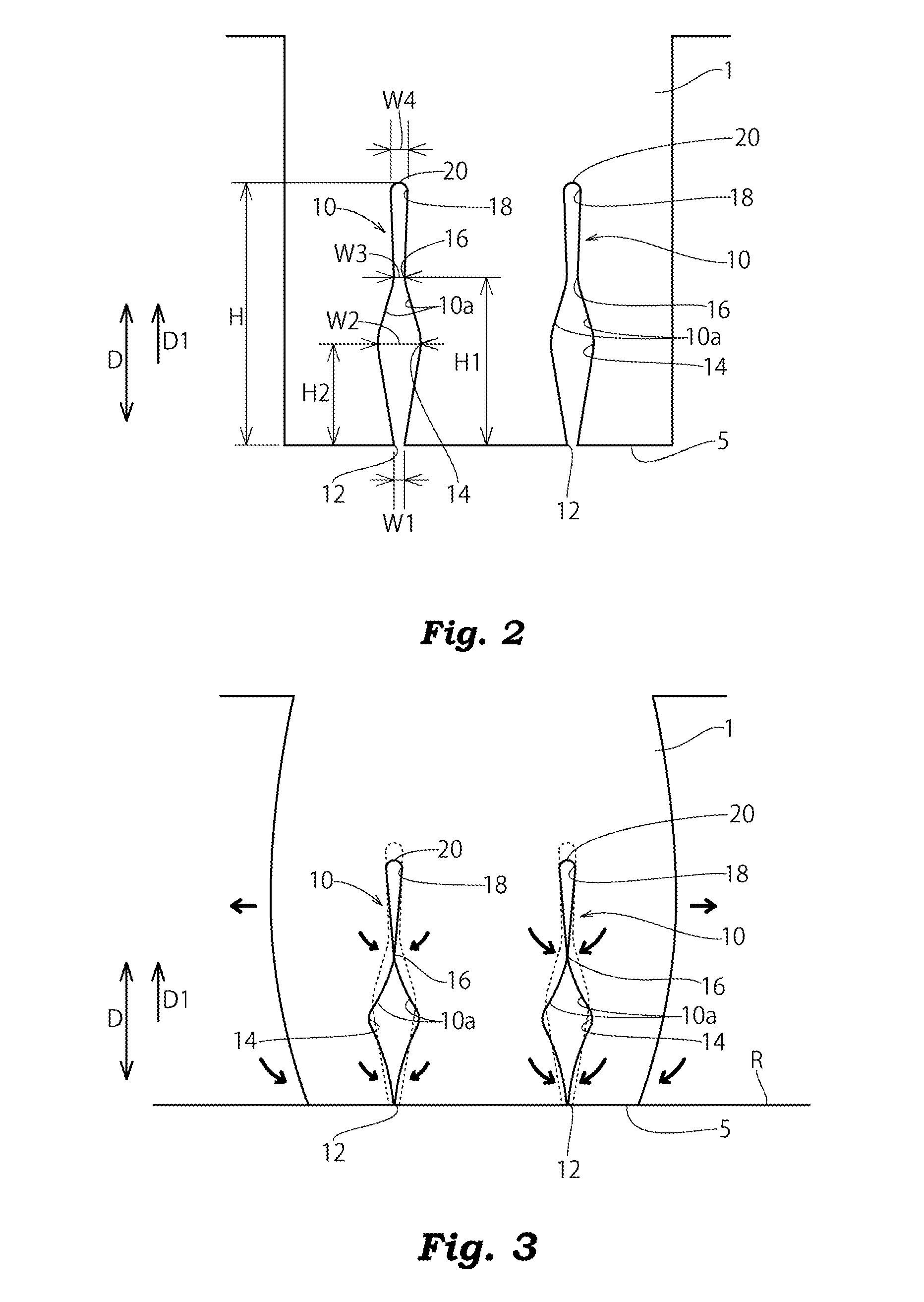
In a pneumatic tire, a sipe formed in a land portion includes a first large width portion having a larger groove width than an opening end formed on a surface of a tread, a neck portion having a smaller groove width than the first large width portion, and a second large width portion having a larger groove width than the neck portion which are disposed in this order on a depth side in a sipe depth direction.
Description
BACKGROUND OF THE INVENTION[0001]1. Field of the Invention[0002]The present invention relates to a pneumatic tire provided with a tread pattern having land portions where sipes are formed.[0003]2. Background Art[0004]Conventionally, for example, slits or slots referred to as sipes are formed on land portions of blocks or ribs of a studless tire thus enabling stable traveling on an icy road surface having a low friction coefficient by making use of an edge effect generated by the sipes. As such a sipe, there has been known a so-called three-dimensional sipe where the shape of the sipe is changed in the depth direction. Linear sipes which open linearly on a tread surface or wavy sipes which open in a wavy form on a tread surface have been proposed in JP-A-2011-157011, JP-A-8-197915 and JP-A-2009-160986, for example.[0005]However, when the number of sipes formed on the land portion is increased, the rigidity of the land portion is lowered so that the land portion falls excessively. Acc...
Claims
Login to View More Application Information
Patent Timeline
 Patent Type & Authority Applications(United States)
IPC IPC(8): B60C11/12
CPCB60C11/1281B60C2200/04B60C11/1204B60C11/11B60C11/1218B60C2011/1209B60C2011/1254
Inventor KAJI, SHINICHI
Owner TOYO TIRE & RUBBER CO LTD