Pneumatic tire

a technology of pneumatic tires and grooves, which is applied in the direction of vehicle components, transportation and packaging, non-skid devices, etc., can solve the problems of difficult to satisfy both, easy to deteriorate even wear resistance, etc., and achieve the effect of enhancing drainage performance, improving the shape of grooves formed in the middle portion, and maintaining uneven wear resistan

Inactive Publication Date: 2012-05-10
SUMITOMO RUBBER IND LTD
View PDF6 Cites 13 Cited by
  • Summary
  • Abstract
  • Description
  • Claims
  • Application Information

AI Technical Summary

Benefits of technology

[0006]The present invention has been accomplished in view of such a problem, and shapes of grooves formed in the middle portion are improved. Based on this, it is a main object of the invention to provide a pneumatic tire capable of enhancing the drainage performance while maintaining uneven wear resistance by securing rigidity of the block.
[0007]In accordance with an aspect of the present invention, a pneumatic tire is provided at a tread portion with a pair of center main grooves which continuously extend on both sides of a tire equator in a tire circumferential direction, and a pair of shoulder main grooves which continuously extend on outer sides of the center main grooves in the tire circumferential direction, thereby dividing the tread portion into a center land portion located between the center main grooves, a middle land portion located between the center main groove and the shoulder main groove, and a pair of shoulder land portions which extend on outer sides of the shoulder main grooves in a tire axial direction. The center main groove is formed into a zigzag shape by connecting arc groove pieces to each other in the tire circumferential direction, each of the arc groove pieces includes an arc portion which is curved to swell toward the tire equator. Such a center main groove can efficiently discharge a water film between a road surface and a portion of the tread portion near the tire equator. Especially, since a zigzag amplitude of the center main groove is 2 to 5% of a tread width, water can efficiently be discharged while securing rigidity of the land portion of the center land portion.
[0008]Further, the middle land portion is provided with a middle inclined groove extending from an intersection portion of the arc groove pieces toward the shoulder main groove at an angle of 12 to 30° with respect to the tire circumferential direction. According to such a middle inclined groove, drainage in the center main groove is guided to the shoulder main groove utilizing rotation of the tie, and the drainage performance can further be enhanced. The middle inclined groove extending at such an angle can exert the drainage function without excessively lowering the rigidity of the middle land portion. Therefore, the uneven wear resistance and the steering stability are maintained.
[0009]A tip end angle of a land portion sandwiched between the middle inclined groove and the center main groove is in a range of 30 to 75°. Hence, a portion of the drainage in the center main groove is smoothly discharged to a last-come side of the center main groove in a tire rotation direction and / or to the middle inclined groove, and it is possible to prevent rigidity of the land portion sandwiched between the middle inclined groove and the center main groove from being lowered. Therefore, the uneven wear resistance and the steering stability are maintained, and the drainage performance is enhanced.
[0010]A groove width of the middle inclined groove is gradually reduced toward a ground-contact end. Such a middle inclined groove increases a flowing speed of water in the middle inclined groove toward the ground-contact end, and enhances lateral rigidity of a region of the middle land portion on an outer side in the axial direction where a ground-contact pressure is increased at the time of cornering. Therefore, the uneven wear resistance and the drainage performance are maintained in well balance.

Problems solved by technology

However, the above-described technique has a problem that since rigidity of the block is lowered, the uneven wear resistance is prone to be deteriorated.
Enhancement of the drainage performance and securement of rigidity of the block are in an antinomic relation, and it is difficult to satisfy both of them.

Method used


Image

  • Pneumatic tire
  • Pneumatic tire
  • Pneumatic tire

Examples


example

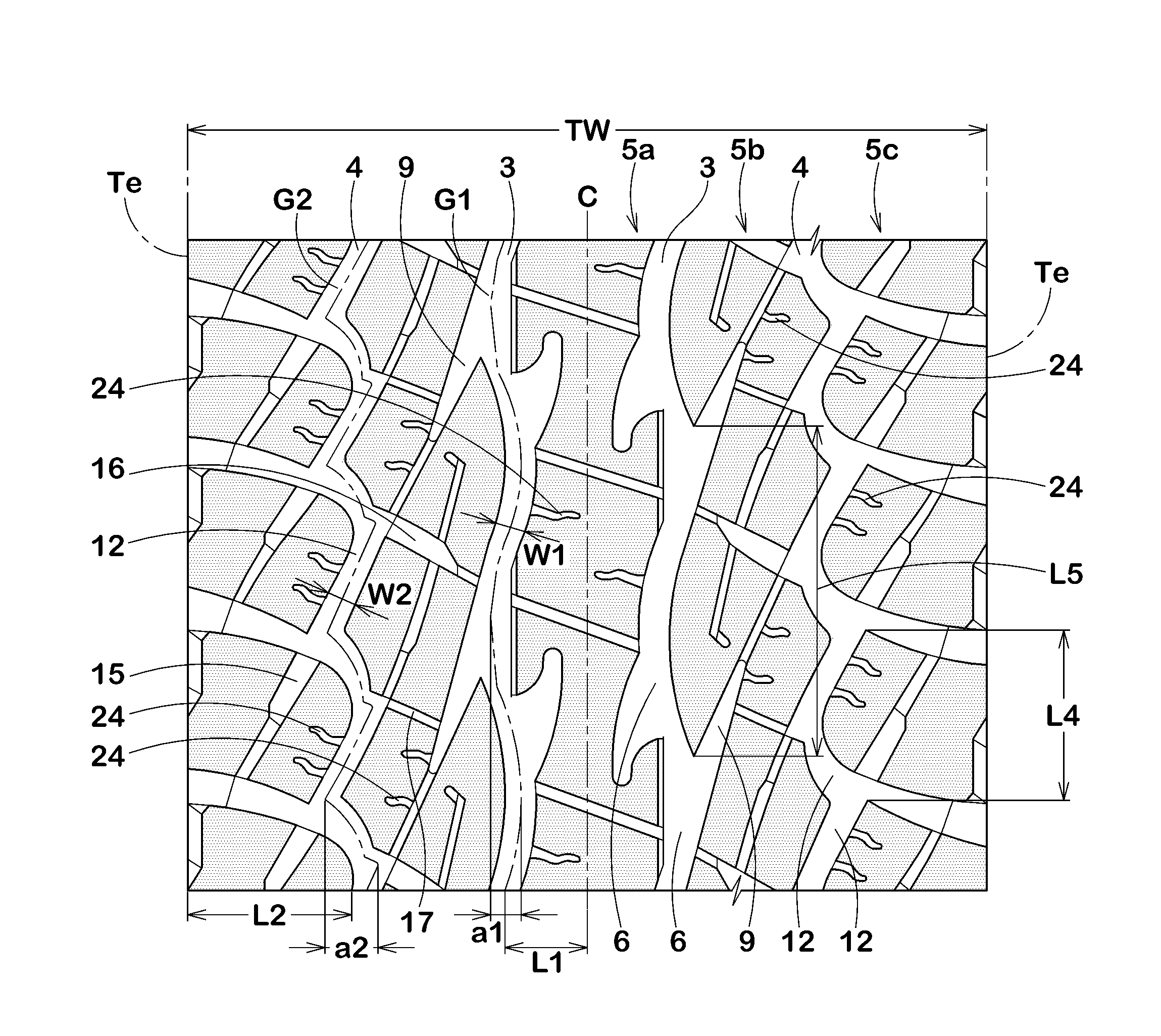
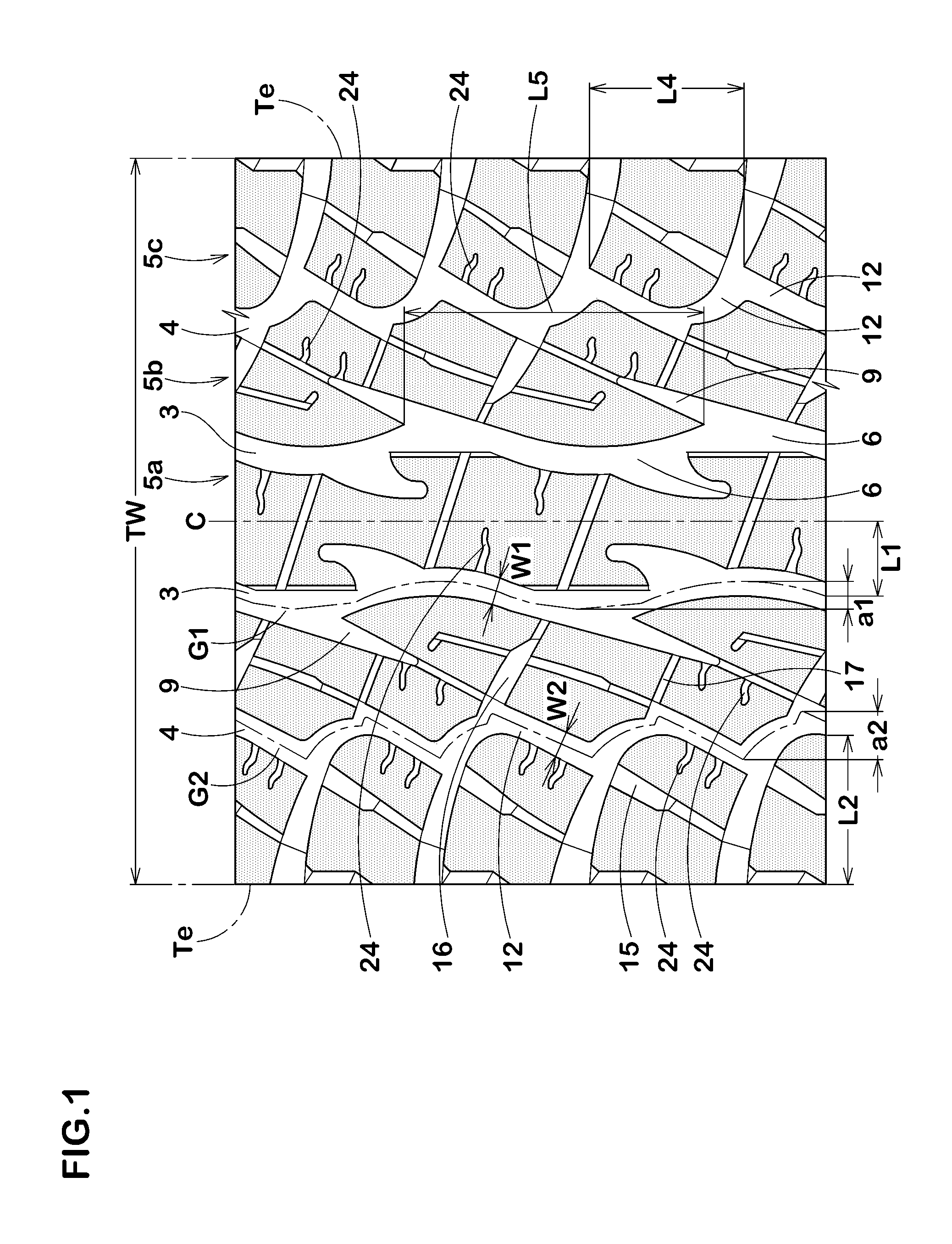
[0065]To confirm the effects of the invention, pneumatic tires (size LT315 / 75R16 121s) having the pattern shown in FIG. 1 were prototyped based on the specification shown in Table 1. Various kinds of performances of them were evaluated. Concrete sizes are as follows. All of conditions except the specification of Table 1 are the same.

[0066]Groove width W1 / ground-contact width TW: 3.5 to 6.0%

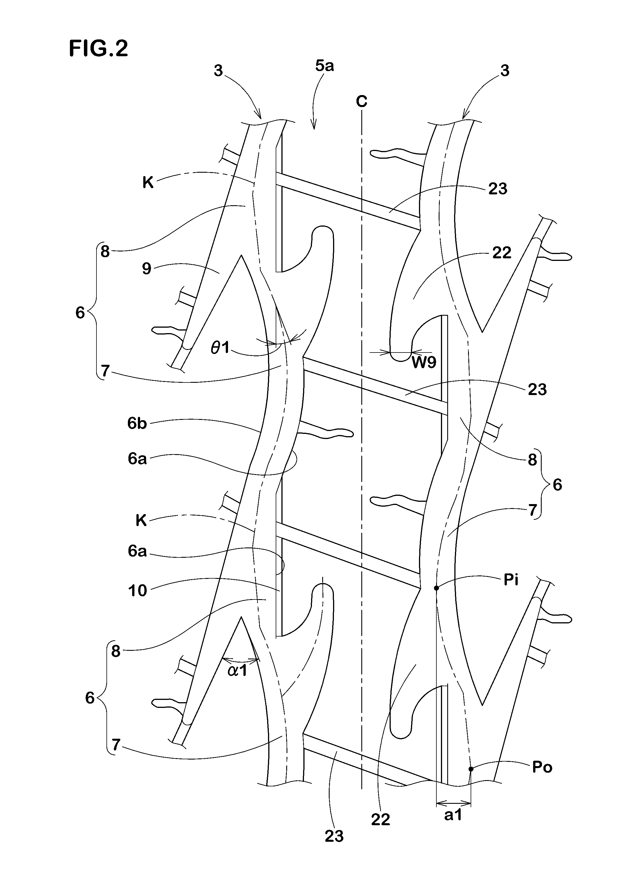
[0067]Groove depth: 12.8 to 13.2 mm

[0068]Angle θ1 with respect to tire circumferential direction: 15 to 25°

[0069]Installation position L1 / TW: 8%

[0070]Groove width W2 / ground-contact width TW: 3.0 to 4.5%

[0071]Groove depth: 12.8 to 13.2 mm

[0072]Angle θ3 with respect to tire circumferential direction: 25 to 35°

[0073]Installation position L2 / TW: 18%

[0074]Groove width W3: 1.6 to 3.6 mm

[0075]Groove depth: 3.0 to 8.2 mm

[0076]Groove width W4: 2.5 to 6.5 mm

[0077]Groove depth: 7.2 to 13.7 mm

[0078]Angle θ4 with respect to tire axial direction: 6.5 to 14.0°

[0079]Groove width W5: 1.3 to 3.2 mm

[0080]Groove dept...


PUM


Abstract

In a pneumatic tire 1, a center land portion 5a between center main grooves 3, a middle land portion 5b between the center main groove 3 and a shoulder main groove 4, and a pair of shoulder land portions 5c extending on outer sides of the shoulder main groove 4 in a tire axial direction are divided from each other. The center main groove 3 includes arc groove pieces 6 which are continuously provided in a tire circumferential direction. The arc groove piece 6 includes an arc portion 7 which is curved to swell toward a tire equator C. The middle land portion 5b is provided with a middle inclined groove 9 which extends from an intersection portion K of the arc groove piece 6 toward the shoulder main groove 4.

Description

BACKGROUND OF THE INVENTION[0001]1. Field of the Invention[0002]The present invention relates to a pneumatic tire in which shapes of grooves formed in a middle portion are improved, thereby enhancing drainage performance while maintaining uneven wear resistance.[0003]2. Description of the Background Art[0004]A pneumatic tire of a block pattern in which a plurality of blocks is formed on a tread portion of the tire is known. In recent years, it is desired to further enhance drainage performance of the pneumatic tire. To enhance the drainage performance, it is necessary to smoothly discharge, toward a ground-contact end, a water film between the tread portion and a road surface, especially a water film near a tire equator. To smoothly discharge such a water film, it is known to increase a width and / or a depth of a groove in a middle portion which lies between the ground-contact end and the tire equator.[0005]However, the above-described technique has a problem that since rigidity of t...

Claims


Application Information

Patent Timeline
Patent Type & Authority Applications(United States)
IPC IPC(8): B60C11/13B60C11/117
CPCB60C11/0302B60C11/11B60C11/0306B60C2011/0372B60C2011/0346B60C2011/0381B60C2011/0388
Inventor TAKANO, HIROKAZU
Owner SUMITOMO RUBBER IND LTD
Why Eureka
Try Eureka