Z-Axis Semiconductor Fluxgate Magnetometer

a magnetometer and fluxgate technology, applied in the field of fluxgate magnetometers, can solve the problems of difficult to attach the two packages together, bulky b>700/b>, and high manufacturing cos

Active Publication Date: 2013-04-25
TEXAS INSTR INC
View PDF3 Cites 20 Cited by
  • Summary
  • Abstract
  • Description
  • Claims
  • Application Information

AI Technical Summary

Problems solved by technology

Although the fluxgate magnetometers 100, 300, 400, 600, and 700 each measures the strength of an external magnetic field, the fluxgate magnetometers 100, 300, 400, 600, and 700 tend to be bulky ...

Method used


Image

  • Z-Axis Semiconductor Fluxgate Magnetometer
  • Z-Axis Semiconductor Fluxgate Magnetometer
  • Z-Axis Semiconductor Fluxgate Magnetometer

Examples


first embodiment

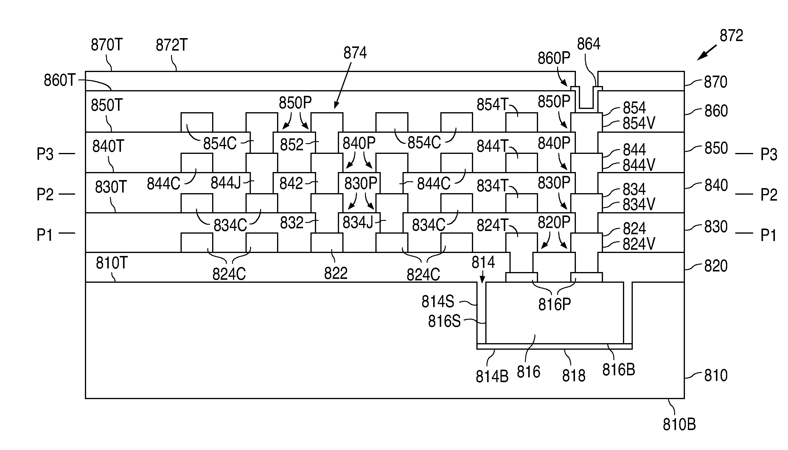
[0086]As shown in FIGS. 16A-16C, in a first embodiment, the metal-1 structures 930 can be formed by depositing a seed layer 932 to touch non-conductive structure 922 and the conductive pads 920. For example, seed layer 932 can be implemented with a layer of aluminum copper. Seed layer 932 can alternately be formed by depositing 300 Å of titanium, 3000 Å of copper, and 300 Å of titanium. After seed layer 932 has been formed, a plating mold 934 is formed on the top surface of seed layer 932.

[0087]As shown in FIGS. 17A-17C, following the formation of plating mold 934, copper is electroplated in a conventional manner to form a number of copper regions 936 approximately 5 μm thick. After the electroplating, as shown in FIGS. 18A-18C, plating mold 934 and the underlying regions of seed layer 932 are removed to form the via structures 930V, the via trace structures 930T, and trace structure 930C.

second embodiment

[0088]Alternately, in a second embodiment, as shown in FIGS. 19A-19C, the metal-1 structures 930 can be formed by first depositing a liner layer 940 on non-conductive structure 922 to line the openings 922P. Liner layer 940 can be implemented with, for example, titanium / titanium nitride. After liner layer 940 has been formed, a metal layer 942, such as tungsten, is conventionally deposited on liner layer 940 to fill up the openings 922P.

[0089]Following this, as shown in FIGS. 20A-20C, metal layer 942 is planarized, such as with chemical-mechanical polishing, to expose the top surface of non-conductive structure 922, and form via plug structures 942P in the openings 922P that make electrical connections to the conductive pads 920 of die 916.

[0090]As shown in FIGS. 21A-21C, after the via plug structures 942P have been formed, a metal layer 944, such as aluminum, is sputter deposited onto non-conductive structure 922 to a depth of approximately 5 μm. Alternately, metal layer 944 can in...


PUM


Abstract

A z-axis fluxgate magnetometer is formed in a semiconductor wafer fabrication sequence, which significantly reduces the size and cost of the fluxgate magnetometer. The semiconductor wafer fabrication sequence forms a vertical magnetic core structure, a first wire structure wound around the magnetic core structure, and a second wire structure wound around the magnetic core structure.

Description

BACKGROUND OF THE INVENTION[0001]1. Field of the Invention[0002]The present invention relates to fluxgate magnetometers and, more particularly, to a z-axis semiconductor fluxgate magnetometer.[0003]2. Description of the Related Art[0004]A magnetometer is a device that measures the strength of an external magnetic field. There are a number of different approaches to measuring magnetic fields, and various different types of magnetometers have been developed based on these different approaches. One type of magnetometer based on flux variations in a magnetic core is a fluxgate magnetometer.[0005]FIG. 1 shows a block diagram that illustrates an example of a prior art fluxgate magnetometer 100. As shown in FIG. 1, fluxgate magnetometer 100 includes a drive coil 110, a sense coil 112, and a magnetic core structure 114 that lies within drive coil 110 and sense coil 112.[0006]As further shown in FIG. 1, fluxgate magnetometer 100 also includes a drive circuit 120 that is connected to drive co...

Claims


Application Information

Patent Timeline
IPC IPC(8): H01L29/82H01L21/02
CPCG01R33/04H01L23/5227H01L24/19H01L28/10H01L23/645H01L2223/6677H01L2224/04105H01L2224/73267H01L2924/15153
Inventor MOHAN, ANURAAGHOPPER, PETER J.
Owner TEXAS INSTR INC
Why Eureka
Try Eureka