Affinity modeling in a data center network

Active Publication Date: 2013-05-02
HEWLETT-PACKARD ENTERPRISE DEV LP
View PDF3 Cites 67 Cited by
  • Summary
  • Abstract
  • Description
  • Claims
  • Application Information

AI Technical Summary

Benefits of technology

[0015]In another aspect, a method of providing enhanced application program performance and network utilization in a network includes modeling an affinity-network topology by a computerized modeling component, and receiving, at a central controller, information pertaining to at least the affinity-network topology. The method further includes co

Problems solved by technology

Although conventional data center networks like those described above have been employed to satisfy the operational requirements of many university, government, business, and financial service entities, such conventional data center networks have drawbacks.
For example, data communications between servers that are not co-located within the same rack may experience excessive delay (also referred to herein as “latency”) within the data center networks, due to the multitude of switches and/or routers that the data may be required to traverse as it propagates “up”, “down”, and/or “across” the hierarchical architecture of the networks.
Data communications between such servers may also experience latency within the respective switches and/or routers of the data center networks due to excessive node and/or link utilization.
Further, because multiple paths may be employed to deliver broadcast and/or multicast data to differe

Method used


Image

  • Affinity modeling in a data center network
  • Affinity modeling in a data center network
  • Affinity modeling in a data center network

Examples


Example

[0039]The disclosures of U.S. Pat. No. ______ filed ______, 2012 entitled DATA CENTER NETWORK ARCHITECTURE (attorney docket no. PLEX-004XX), U.S. Pat. No. ______ filed ______, 2012 entitled CONTROL AND PROVISIONING IN A DATA CENTER NETWORK WITH AT LEAST ONE CENTRAL CONTROLLER (attorney docket no. PLEX-006XX), U.S. Pat. No. ______ filed ______, 2012 entitled HIERARCHY OF CONTROL IN A DATA CENTER NETWORK (attorney docket no. PLEX-007XX), U.S. Provisional Patent Application No. 61 / 554,107 filed Nov. 1, 2011 entitled DATA CENTER NETWORK SWITCHING, U.S. patent application Ser. No. 13 / 528,501 filed Jun. 20, 2012 entitled OPTICAL ARCHITECTURE AND CHANNEL PLAN EMPLOYING MULTI-FIBER CONFIGURATIONS FOR DATA CENTER NETWORK SWITCHING, and U.S. patent application Ser. No. 13 / 528,211 filed Jun. 20, 2012 entitled OPTICAL JUNCTION NODES FOR USE IN DATA CENTER NETWORKS, are incorporated herein by reference in their entirety.

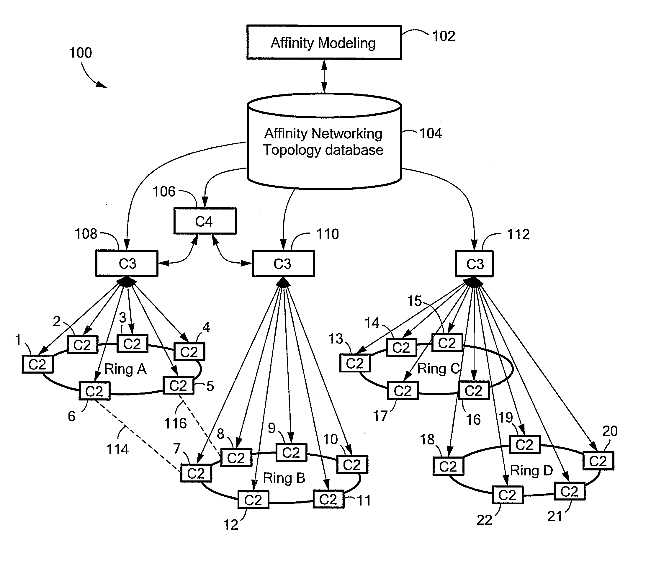
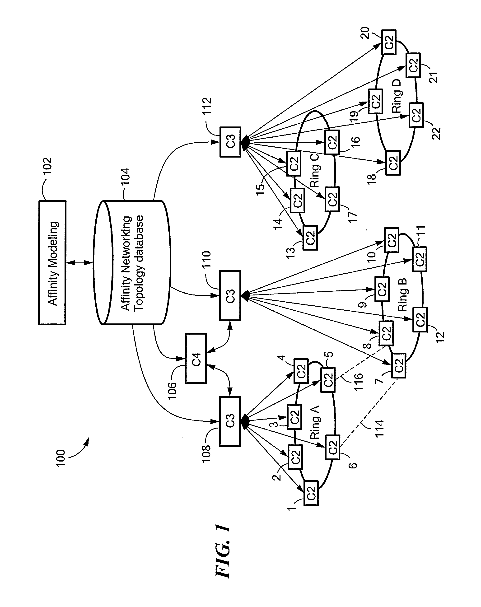
[0040]Systems and methods of affinity modeling in data center networks are d...


PUM


Abstract

Systems and methods of affinity modeling in data center networks that allow bandwidth to be efficiently allocated with the data center networks, while reducing the physical interconnectivity requirements of the data center networks. Such systems and methods of affinity modeling in data center networks further allow computing resources within the data center networks to be controlled and provisioned based at least in part on the network topology and an application component topology, thereby enhancing overall application program performance.

Description

CROSS REFERENCE TO RELATED APPLICATIONS[0001]This application claims benefit of the priority of U.S. Provisional Patent Application No. 61 / 554,107 filed Nov. 1, 2011 entitled DATA CENTER NETWORK SWITCHING. This application is a continuation-in-part of U.S. patent application Ser. No. 13 / 528,501 filed Jun. 20, 2012 entitled OPTICAL ARCHITECTURE AND CHANNEL PLAN EMPLOYING MULTI-FIBER CONFIGURATIONS FOR DATA CENTER NETWORK SWITCHING, and a continuation-in-part of U.S. patent application Ser. No. 13 / 528,211 filed Jun. 20, 2012 entitled OPTICAL JUNCTION NODES FOR USE IN DATA CENTER NETWORKS.STATEMENT REGARDING FEDERALLY SPONSORED RESEARCH OR DEVELOPMENT[0002]Not applicableFIELD OF THE INVENTION[0003]The present disclosure relates generally to data center network architectures and switching technologies, and more specifically to data center networks that can employ optical network topologies and optical nodes to efficiently allocate bandwidth within the data center networks, while reducin...

Claims


Application Information

Patent Timeline
IPC IPC(8): H04B10/08H04L45/122
CPCH04Q3/0083H04L41/34H04L41/12H04B10/27H04L45/20H04Q11/0066H04Q2011/0047H04Q2011/009
Inventor SRINIVAS, ANANDHUSAK, DAVID J.DERUIJTER, DENIS H.
Owner HEWLETT-PACKARD ENTERPRISE DEV LP
Why Eureka
Try Eureka