Oscillating device

Active Publication Date: 2013-05-09
SITRONIX TECH CORP
View PDF13 Cites 7 Cited by
  • Summary
  • Abstract
  • Description
  • Claims
  • Application Information

AI Technical Summary

Benefits of technology

[0005]An objective of the present invention is to provide an oscillating device. By making a bias current produced by a second driving voltage proportional to a bias of an oscillating module, simple compensation for temperature and process can be performed. Thereby, the frequency can be tuned using a few calibration bits.
[0006]Another objective of the present invention is to provide an oscillating device. By using a voltage regulating circuit for producing a stable voltage as the power source for a driving module and an oscillating module, the influence of the voltage of the power supply on the oscillating frequency can be reduced.
[0007]The oscillating device according to the present invention comprises a driving module and an oscillating module. The driving module is used for producing a first driving voltage and a second driving voltage. The oscillating module is coupled to the driving module, and comprises a first symmetric load circuit, a second symmetric load circuit, and a bias circuit. The first symmetric load circuit and the second symmetric load circui

Problems solved by technology

This is because the error in the frequency of a quartz oscillator is extremely small.
Nonetheless, the use of the quartz oscillator increases the overall system cost.
For high-

Method used


Image

  • Oscillating device
  • Oscillating device
  • Oscillating device

Examples


Embodiment Construction

[0016]In order to make the structure and characteristics as well as the effectiveness of the present invention to be further understood and recognized, the detailed description of the present invention is provided as follows along with embodiments and accompanying figures.

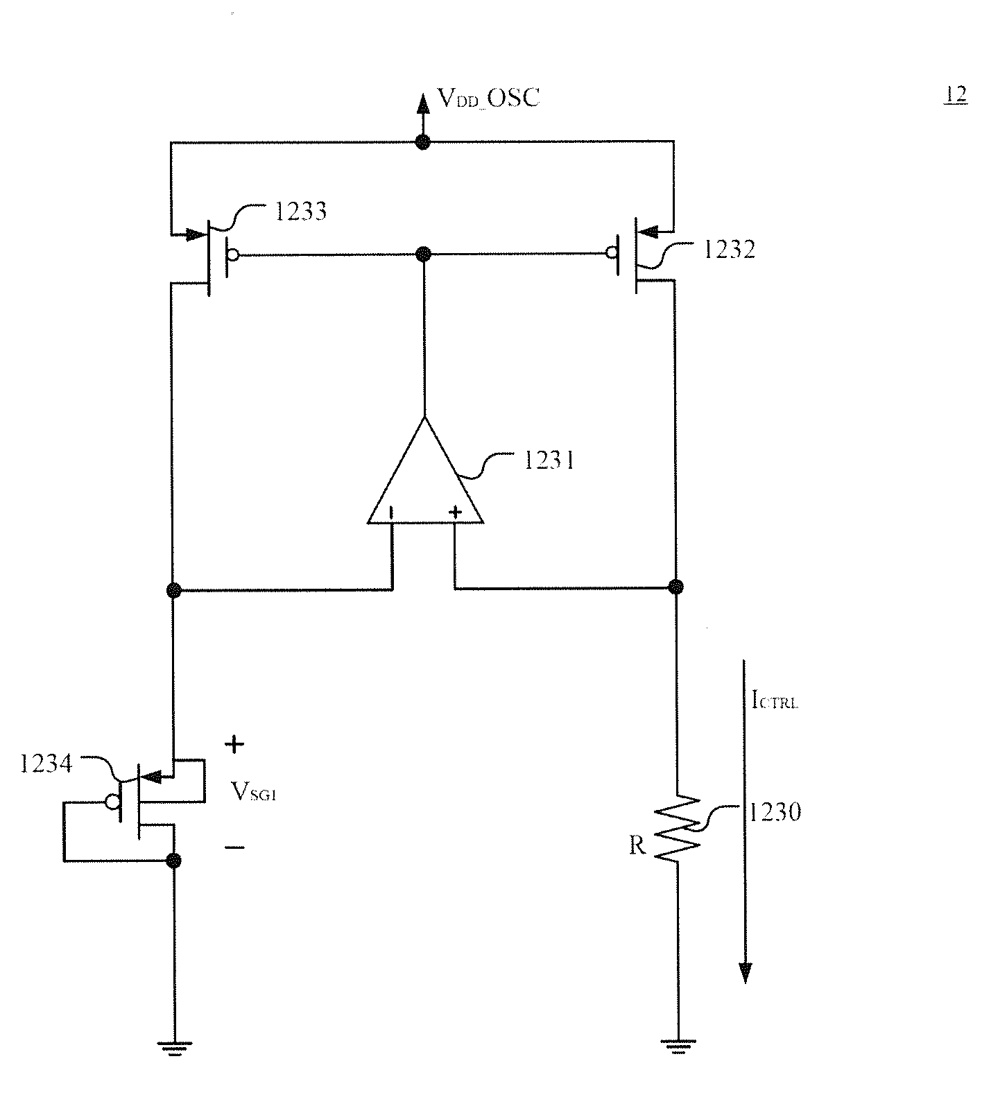
[0017]FIG. 3 shows a block diagram of the oscillating device according an embodiment of the present invention. As shown in the figure, the oscillating device 1 according to the present invention comprises a driving module 10 and an oscillating module 20. The driving module 10 is used for producing a first driving voltage VBP and a second driving voltage VBN. The oscillating module 20 is coupled to the driving module 10 and has a first symmetric load circuit 222, a second symmetric load circuit 224, and a bias circuit 220, as shown in FIG. 4. The first symmetric load circuit 222 produces a first bias VSG1 according to the first driving voltage VBP; the second symmetric load circuit 224 produces a first bias VSG2 acc...


PUM


Abstract

The present invention relates to an oscillating device, which comprises a driving module and an oscillating module. The driving module is used for producing a first driving voltage and a second driving voltage. The oscillating module comprises a first symmetric load circuit, a second symmetric load circuit, and a bias circuit. The first symmetric load circuit and the second symmetric load circuit produce a bias according to the first driving voltage. The bias circuit produces a bias current according to the second driving voltage. The oscillating module produces an oscillating signal according to the first driving voltage and the bias current, where the bias current is proportional to the bias. Thereby, by making the driving signal produced by driving module proportional to the bias of the oscillating module, simple compensation for temperature and process can be performed. Thereby, the frequency can be tuned using a few calibration bits.

Description

FIELD OF THE INVENTION[0001]The present invention relates generally to an oscillating device, and particularly to an oscillating device having process and temperature compensation.BACKGROUND OF THE INVENTION[0002]The clock frequency output by an oscillator plays an extremely important role in a digital circuit. Different systems have different requirements for the clock frequency. If a very stable and accurate frequency is required, a quartz oscillator is usually adopted as the reference source for the reference clock. This is because the error in the frequency of a quartz oscillator is extremely small. Besides, the influence of temperature of the oscillating frequency is also very small. Nonetheless, the use of the quartz oscillator increases the overall system cost. If a sufficiently accurate (capable of calibrating to a certain accuracy) oscillator can be implemented in a chip and the drift of the oscillating frequency by temperature is small enough, then the quartz oscillator ca...

Claims


Application Information

Patent Timeline
IPC IPC(8): H03L7/00
CPCH03K3/011H03K3/023H03B5/24H03K3/0322
Inventor HUNG, CHIH-TEYEH, CHENG-CHUNG
Owner SITRONIX TECH CORP
Why Eureka
Try Eureka