Method for monitoring wavelength of tunable laser on user end by optical line terminal on local end

US20170170898A1Active Publication Date: 2017-06-15ACCELINK TECHNOLOGIES CO LTD

Image

  • Method for monitoring wavelength of tunable laser on user end by optical line terminal on local end
  • Method for monitoring wavelength of tunable laser on user end by optical line terminal on local end
  • Method for monitoring wavelength of tunable laser on user end by optical line terminal on local end

Examples


Embodiment Construction

[0033]The accompanying drawings and the following examples are used for further illustrating the concept of the present invention.

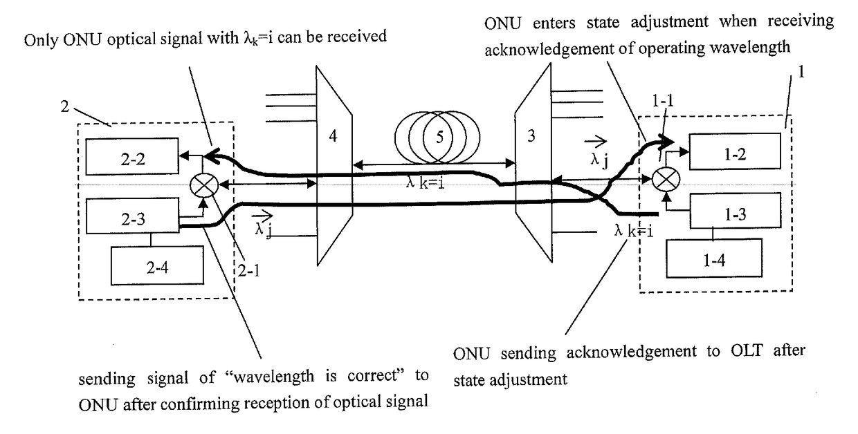
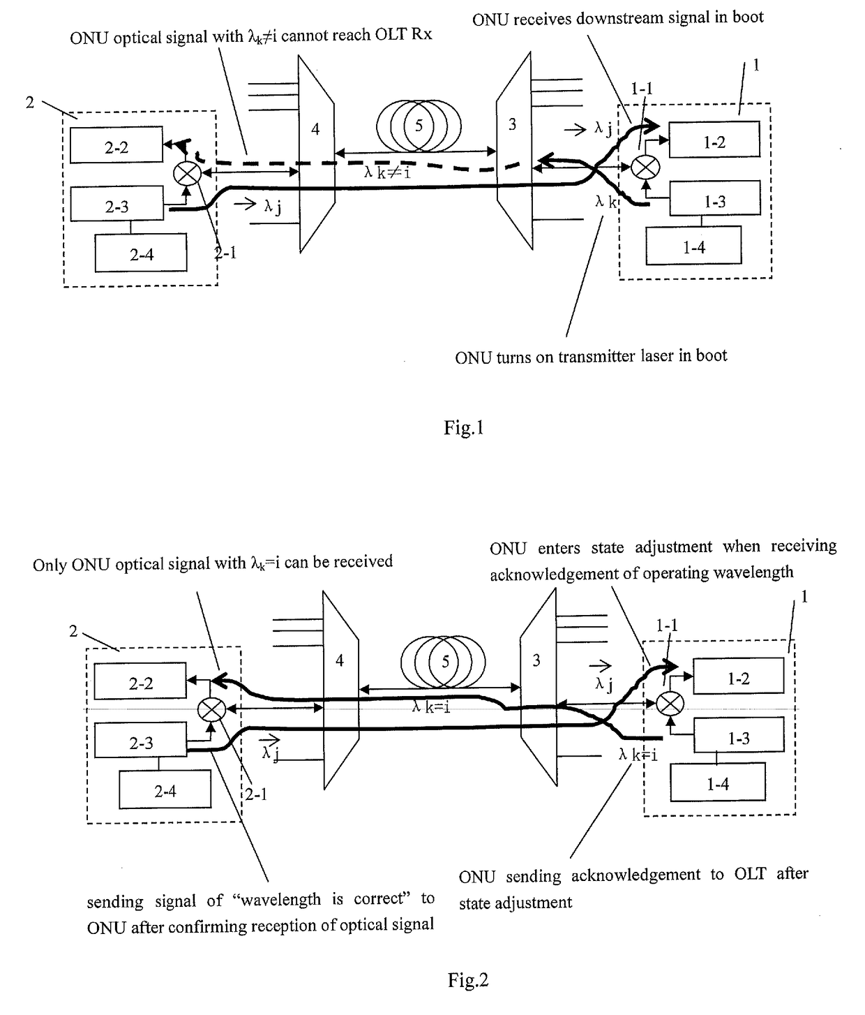
[0034]FIG. 1 shows the WDM-PON network architecture which the method of embodiments of the present invention is based on. The WDM-PON network architecture comprises ONU 1 at user end, OLT 2 at local end, a first athermal arrayed waveguide grating 3, a second athermal arrayed waveguide grating 4, transmission fiber 5, wherein ONU 1 is connected with the first athermal arrayed waveguide grating 3, which is connected with the second athermal arrayed waveguide grating 4 via the transmission fiber 5, the second athermal arrayed waveguide grating 4 is connected with the OLT 2 at local end. ONU 1 comprises an optical receiver 1-1, C / L-WDM 1-2, wavelength tunable optical transmitter 1-3, ONU controller 1-4. OLT 2 comprises an OLT optical receiver 2-1, C / L-WDM 2-2, OLT optical transmitter 2-3, OLT controller 2-4. The first athermal arrayed waveguide grating 3 and ...


PUM


Abstract

Disclosed is a method for monitoring the wavelength of a tunable laser device of user by local OLT. The method is applied to a wavelength division multiplexing passive optical network framework. The framework comprises an ONU, a first athermal array waveguide grating, a transmission optical fiber, a second athermal array waveguide grating and the OLT, which are sequentially connected. ONU comprises tunable wavelength optical transmitters. The method comprises: starting handshaking is carried out between the OLT and the ONU; and the OLT carries out wavelength drifting monitoring during operation of the ONU. Wavelength adjustment can be carried out on the multi-channel tunable laser device in an external auxiliary monitoring environment, thus channel wavelengths of the multi-channel tunable laser device can be accurately controlled, and the requirement for calibration accuracy of channels of the tunable laser device at the ONU is greatly reduced.

Description

TECHNICAL FIELD[0001]Embodiments of the present invention relate to a method for monitoring the wavelength of a tunable laser during ONU (Optical Network Unit) is booting and running, and more particularly to a control method for monitoring the wavelength of a tunable laser of ONU on user end in real time in WDM-PON (Wavelength Division Multiplexing-Passive Optical Network), to ensure its operation wavelength is correct, which is belonged to field of communication.BACKGROUND OF THE INVENTION[0002]WDM-PON access network technologies have been developed for many years, a technical bottleneck of which is about colorless ONU module. Earlier technology on colorless ONU module based on injection-locked multichannel laser has been proven unsuitable for use in high-rate. In recent years, with the increasing requirements on access bandwidth, WDM-PON access network has been turning to use multi-channel tunable lasers to realize function of colorless ONU.[0003]As known in the art, the multi-ch...

Claims


Application Information

Patent Timeline
15 Jun 2017
Publication
US20170170898A1
IPC
H04B10/079; H04J14/02
CPC
H04B10/07957; H04J14/02; H04B10/0799; H04B10/0731; H04B10/079; H04J14/00; H04J14/0282
Inventors
FU, YANFENG; HU, QIANGGAO