Control system of electric motor

a control system and electric motor technology, applied in the direction of electric generator control, dynamo-electric converter control, dynamo-electric gear control, etc., can solve the problems of lowering prone to failure, and prone to failure, so as to reduce the working efficiency of the motor, the fluctuation of the battery voltage can be easily tracked or controlled, and the control accuracy is low.

Inactive Publication Date: 2002-12-19
NISSAN MOTOR CO LTD
View PDF6 Cites 11 Cited by
  • Summary
  • Abstract
  • Description
  • Claims
  • Application Information

AI Technical Summary

Benefits of technology

0006] That is, under a normal condition of the control system, an optimum current command map is selected in accordance with the battery voltage to derive a current command. However, in case of a marked change of the motor torque, that is, in case wherein fluctuation of the current command becomes marked, the battery voltage becomes varied temporarily due to output fluctuation of the motor, so that the voltage is subjected to a voltage drop prior to switching of the current command maps. In this case, the control system tends to lower the control accuracy. If, for suppressing lowering of control accuracy, margins are provided to the current command maps, working efficiency of the motor becomes lowered inevitably.
0007] If a feedback cycle is made shorter, that is, if the interval at which torque command and rotation speed data of the motor are issued is made shorter, the fluctuation of battery voltage can be easily tracked or controlled. However, this measure needs addition of a noise cut filter for removing noises which are inevitably produced when monitoring the battery voltage, and thus the measure brings about lowering in tracking ability. In addition to this, the load of the control system becomes larger.

Problems solved by technology

In this case, the control system tends to lower the control accuracy.
If, for suppressing lowering of control accuracy, margins are provided to the current command maps, working efficiency of the motor becomes lowered inevitably.
However, this measure needs addition of a noise cut filter for removing noises which are inevitably produced when monitoring the battery voltage, and thus the measure brings about lowering in tracking ability.
In addition to this, the load of the control system becomes larger.

Method used


Image

  • Control system of electric motor
  • Control system of electric motor
  • Control system of electric motor

Examples


first embodiment

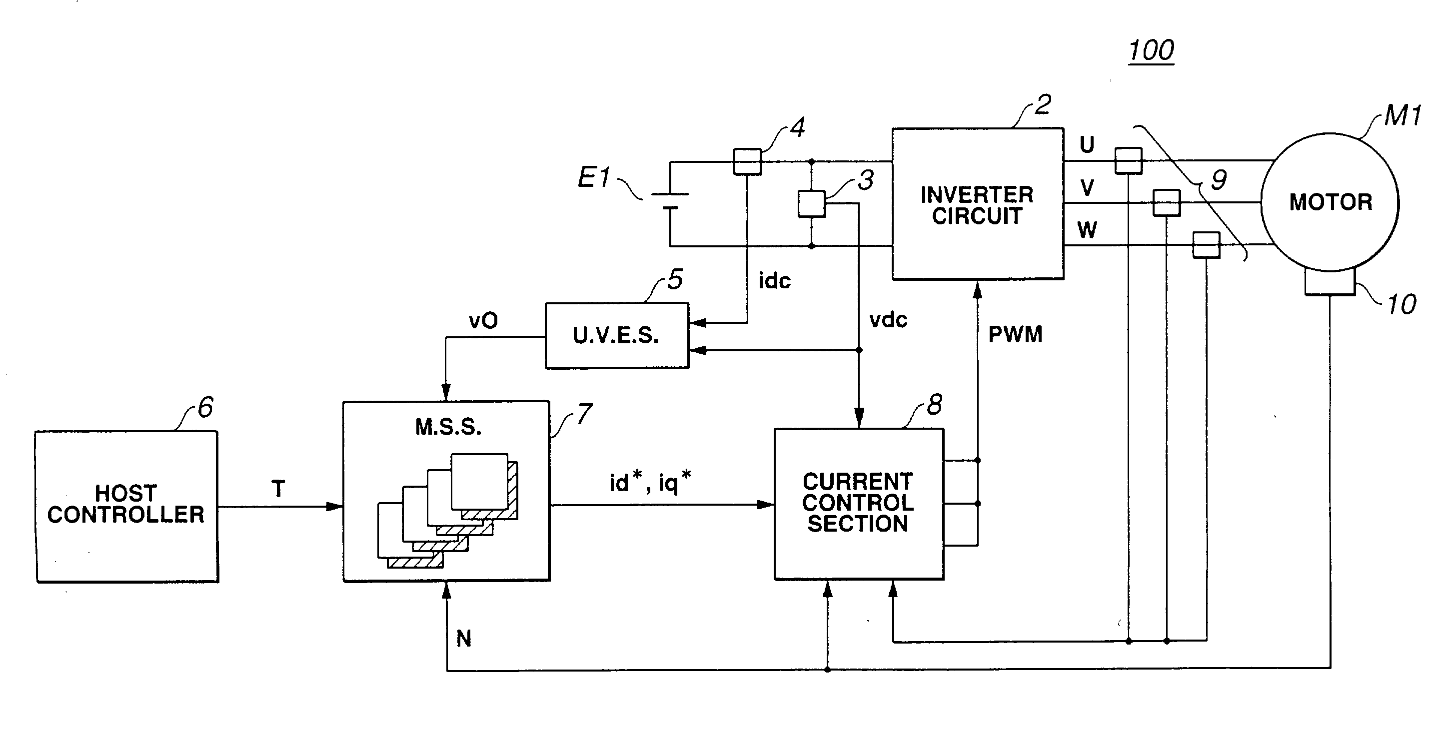
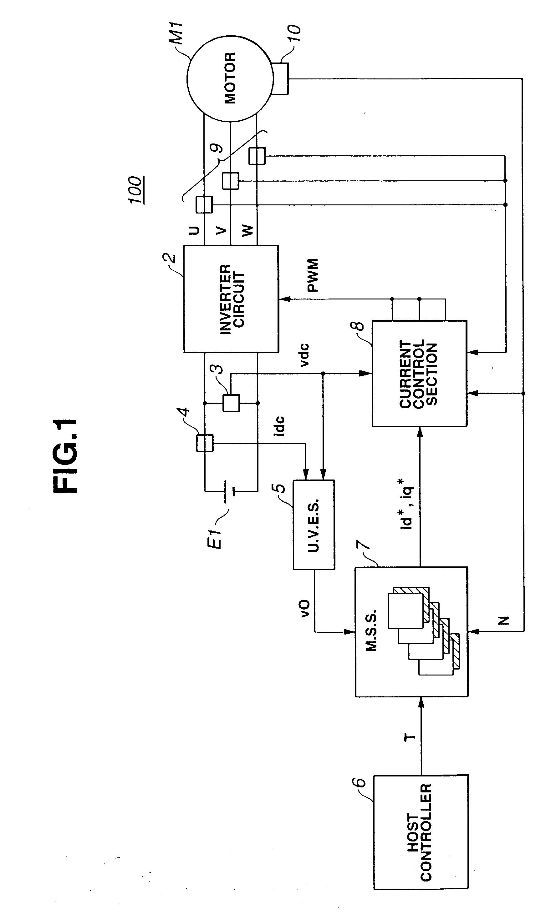
[0020] Referring to FIG. 1, there is schematically shown a control system 100 of an electric motor "M1", which is the present invention.

[0021] The motor "M1" is of a synchronous type. That is, the control system 100 is arranged to control operation of the synchronous motor "M1".

[0022] The control system 100 comprises an inverter circuit 2 that inverts or converts a direct current from a battery "E1" to a three-phase alternating current which is fed to synchronous motor "M1", a voltmeter 3 that detects a magnitude "vdc" of an output voltage of battery "E1", and an ammeter 4 that detects a magnitude "idc" of output current from battery "E1".

[0023] Furthermore, the control system 100 comprises an unloaded voltage estimation section (or U. V. E. S) 5 that, based on the detected voltage "vdc" from voltmeter 3 and the detected current "idc" from ammeter 4, estimates an output voltage "v0" that would be outputted from battery "E1" when battery is unloaded, a current sensor 9 that detects a...

second embodiment

[0063] Referring to FIG. 4, there is shown schematically a control system 200 of an electric motor "M1", which is the present invention.

[0064] Since the second embodiment 200 is similar to the above-mentioned first embodiment 100, only portions or parts which are different from those of the first embodiment 100 will be described in detail in the following.

[0065] As shown, in the second embodiment 200, there is employed a current command setting section 22 which includes an unloaded voltage estimation part (or U. V. E. P.) 22a and a map storing part (or M. S. P.) 22b. However, in the second embodiment 200, there is no means corresponding to ammeter 4 employed in the first embodiment 100.

[0066] FIG. 5 shows schematically current command maps installed or memorized in map storing part 22b of current command setting section 22. As shown, each map indicates d-axis current command "id*", q-axis current command "iq*" and direct current voltage "vdc'" with respect to torque command "T" (Nm)...


PUM


Abstract

A control system of an electric motor powered by a battery comprises an inverter circuit that inverts a direct current fed from the battery to an alternating current fed to the electric motor; and an output controlling circuit that controls an output of the inverter circuit to adjust operation of the electric motor. The output controlling circuit includes a first section that detects a magnitude of output voltage of the battery; a second section that, based on the detected output voltage, derives an unloaded voltage that would be outputted from the battery when the battery is unloaded; a third section that, based on the unloaded voltage, looks up an appropriate current command from maps that store various current commands with respect to operation condition of the motor; and a fourth section that, based on the looked up current command, controls the output of the inverter circuit.

Description

BACKGROUND OF INVENTION[0001] 1. Field of Invention[0002] The present invention relates in general to control systems of electric motors and more particularly to control systems of a type that inverts direct current from a battery to alternating current to power an electric motor. More specifically, the present invention is concerned with a technique that effectively uses a direct current power source for powering an electric motor.[0003] 2. Description of Related Art[0004] Hitherto, various control systems of electric motors have been proposed and put into practical use. One of them is described in Laid-Open Japanese Patent Application (Tokkai) 2000-32799. In the control system of this publication, for various different voltages from a battery, there are provided respective current command maps listing high-efficiency data in advance by torque commands and rotation speeds of the motor, and according to the voltage actually applied to the motor, an optimum one of the current command...

Claims


Application Information

Patent Timeline
Patent Type & Authority Applications(United States)
IPC IPC(8): H02P21/14H02P21/00H02P21/22H02P23/14H02P27/04H02P27/08
CPCH02M7/53873H02P29/026H02P6/002H02P6/28
Inventor KARIKOMI, TAKAAKI
Owner NISSAN MOTOR CO LTD
Why Eureka
Try Eureka