
Adaptive Learning System and Method of Vane Position for a Variable Geometry Turbocharger

a learning system and variable geometry technology, applied in the direction of electric control, combustion engines, machines/engines, etc., can solve the problems of reducing the control accuracy of variable geometry, insufficient accuracy to provide accurate, and increasing the complexity of the overall system, so as to improve accuracy, accurately estimate the vane position throughout the vehicle operation, and accurate estimate the effect of the accuracy

Active Publication Date: 2008-12-04
FORD GLOBAL TECH LLC
View PDF39 Cites 13 Cited by
  • Summary
  • Abstract
  • Description
  • Claims
  • Application Information

AI Technical Summary

Benefits of technology

[0001]Vehicle engine systems may include variable geometry turbochargers to supply compressed air and recirculated exhaust gas to the cylinders of the engine to increase operating efficiency, reduce emissions, and improve performance of the engine system. The variable geometry turbocharger may include vane(s) that may be adjusted via an actuator to alter the geometry of the turbine housing which in turn may affect exhaust flow of the variable geometry turbocharger. For example, at lower engine speeds with lower exhaust flow, the vanes may be adjusted to decrease the area of the variable geometry turbocharger intake in order to accelerate the exhaust gas causing the turbocharger turbine to spin faster thus reducing spool up time. As another example, at higher engine speeds with higher exhaust flow, the vanes may be adjusted to increase the area of the variable geometry turbocharger intake so as not to inhibit exhaust flow thus improving the efficiency of the variable geometry turbocharger. Accordingly, the vane(s) of the variable geometry turbocharger may be adjusted across the operating range of the engine system to increase efficiency of the variable geometry turbocharger.
[0002]A vane position sensor may be implemented to measure the position of the vane(s) in the variable geometry turbocharger so that accurate control of the variable geometry turbocharger may be achieved. However, degradation of the position sensor over time may decrease control accuracy of the variable geometry turbocharger, and may necessitate additional sensor diagnostics which can add considerable complexity to the overall system.
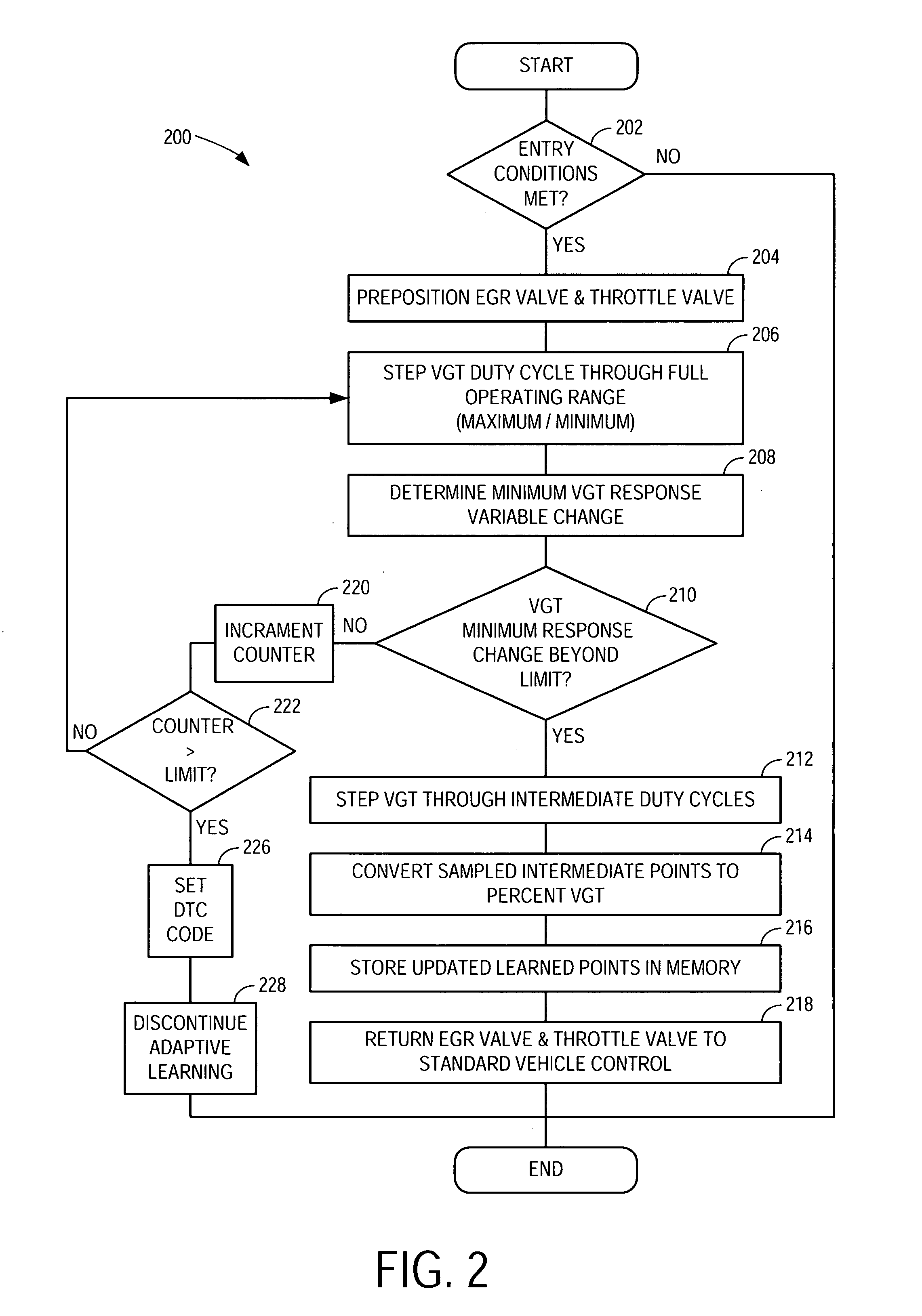
[0006]In this way, aspects of engine operation may be controlled based on a vane position of a variable geometry turbocharger that may be accurately estimated without the need for a sensor to measure vane position (although a sensor additionally may be used, if desired to further improve accuracy). In other words, by intrusively stepping the vane through substantially the entire operating range from minimum to maximum (or maximum to minimum), the vane position may be repeatedly calibrated to a response parameter that may be used to accurately estimate vane position throughout vehicle operation.
[0007]Furthermore, an engine system that includes a vane position sensor may be made more robust by comparing the estimated vane position with a measured vane position in order to detect sensor performance degradation. In some embodiments, the inferred vane position may be used to infer an exhaust back pressure and exhaust system operation may be adjusted based on the inferred exhaust back pressure. Thus, by accurately inferring exhaust back pressure the need for an exhaust back pressure sensor may be eliminated and engine system robustness may be improved.BRIEF

Problems solved by technology

However, degradation of the position sensor over time may decrease control accuracy of the variable geometry turbocharger, and may necessitate additional sensor diagnostics which can add considerable complexity to the overall system.
However, the inventors herein have recognized some issues relating to the above approach.
In particular, the above approach requires a sensor to measure exhaust back pressure, and such a sensor may not be present, or may be of insufficient accuracy to provide accurate position sensor estimation.

Method used


Image

  • Adaptive Learning System and Method of Vane Position for a Variable Geometry Turbocharger
  • Adaptive Learning System and Method of Vane Position for a Variable Geometry Turbocharger
  • Adaptive Learning System and Method of Vane Position for a Variable Geometry Turbocharger

Examples


Embodiment Construction

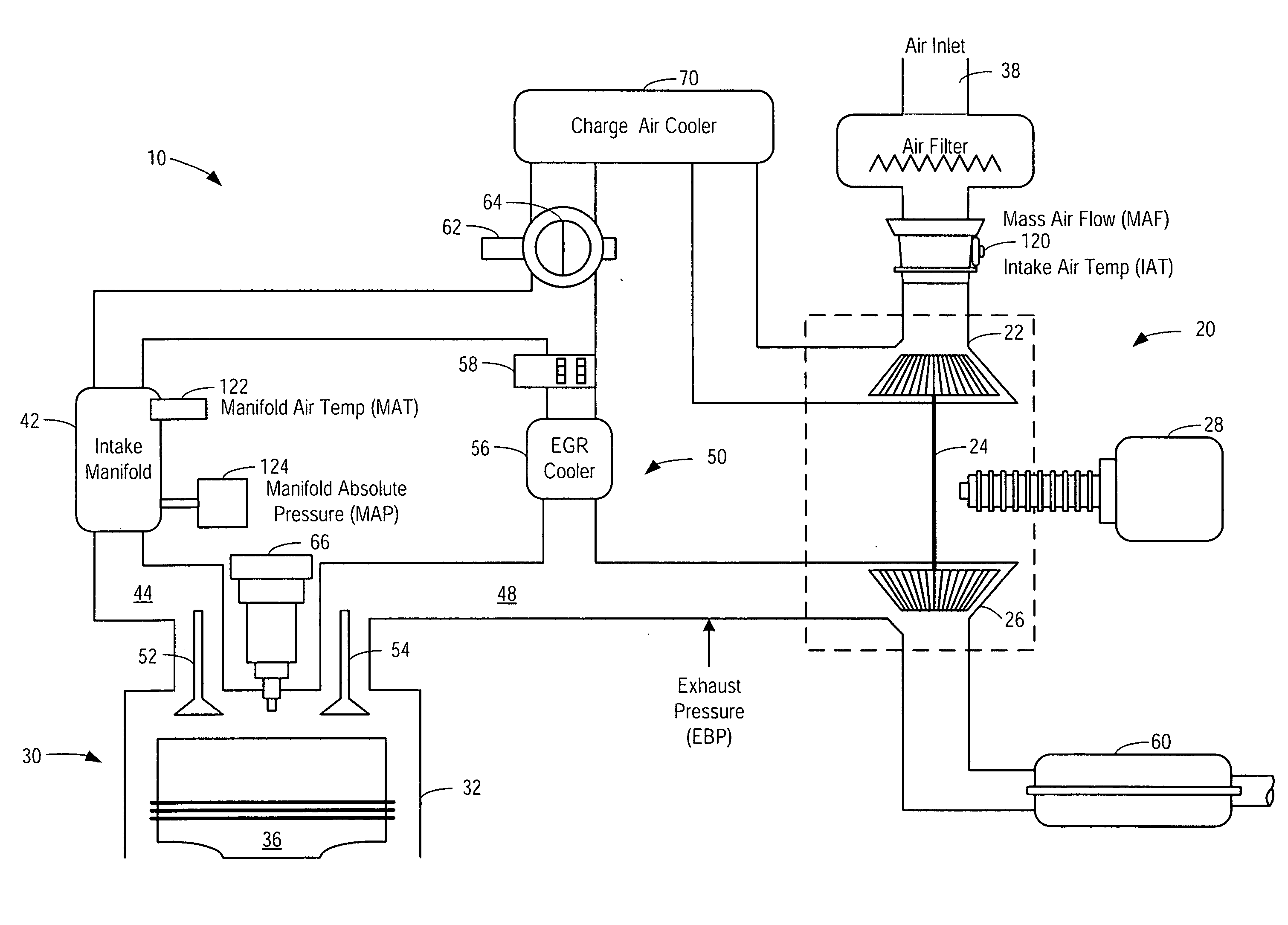
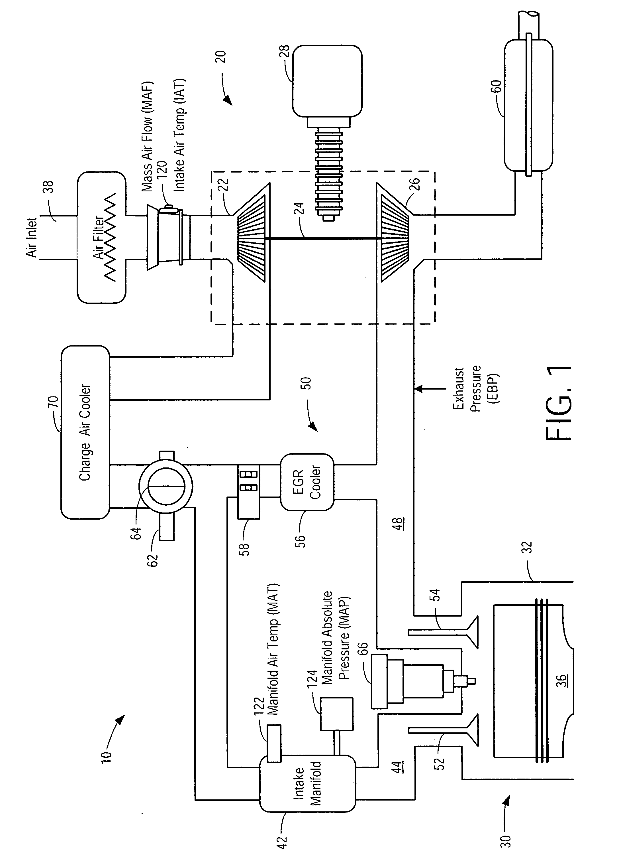
[0013]FIG. 1 is a schematic diagram showing one cylinder of multi-cylinder engine 10, which may be included in a propulsion system of an automobile. Combustion chamber (i.e. cylinder) 30 of engine 10 may include combustion chamber walls 32 with piston 36 positioned therein. Combustion chamber 30 may receive intake air from intake passage 44 via intake manifold 42 and may exhaust combustion gases via exhaust passage 48. Intake passage 44 and exhaust passage 48 can selectively communicate with combustion chamber 30 via respective intake valve 52 and exhaust valve 54. In some embodiments, combustion chamber 30 may include two or more intake valves and / or two or more exhaust valves.

[0014]In some embodiments, intake valve 52 and exhaust valve 54 may be controlled via electric valve actuation (EVA). Further in some embodiments, one or more of the intake and exhaust valves may be actuated by one or more cams, and may utilize one or more of cam profile switching (CPS), variable cam timing (...


PUM


Abstract

A method of operation for an engine system having a variable geometry turbocharger with a vane, the vane having a variable position is provided. The method includes adjusting a vane of the variable geometry turbocharger through a range of operation by stepping through a plurality of vane positions and holding at each of the plurality of positions, the range spanning from a substantially minimum position to a substantially maximum position of the variable geometry turbocharger, and adjusting operation of the engine based on a response to the vane adjustment.

Description

BACKGROUND AND SUMMARY [0001]Vehicle engine systems may include variable geometry turbochargers to supply compressed air and recirculated exhaust gas to the cylinders of the engine to increase operating efficiency, reduce emissions, and improve performance of the engine system. The variable geometry turbocharger may include vane(s) that may be adjusted via an actuator to alter the geometry of the turbine housing which in turn may affect exhaust flow of the variable geometry turbocharger. For example, at lower engine speeds with lower exhaust flow, the vanes may be adjusted to decrease the area of the variable geometry turbocharger intake in order to accelerate the exhaust gas causing the turbocharger turbine to spin faster thus reducing spool up time. As another example, at higher engine speeds with higher exhaust flow, the vanes may be adjusted to increase the area of the variable geometry turbocharger intake so as not to inhibit exhaust flow thus improving the efficiency of the va...

Claims


Application Information

Patent Timeline
Patent Type & Authority Applications(United States)
IPC IPC(8): F02D23/00
CPCF02B37/24F02D41/0007F02D41/0055F02D41/1448F02D41/2438F02D41/2441F02D41/2464F02D2200/0406Y02T10/144Y02T10/47Y02T10/12Y02T10/40
Inventor ROLLINGER, JOHN ERICBELL, DAVIDCULLEN, MICHAEL JOHNFULTON, BRIEN LLOYD
Owner FORD GLOBAL TECH LLC
Learn More