Apparatus and process for optimizing work from a smart material actuator product

a technology of smart material actuators and actuators, applied in the direction of device details, device material selection, piezoelectric/electrostrictive device details, etc., can solve the problems of reducing difficult to achieve objectives, etc., to reduce the effective life of the mechanism, optimize the performance of the smart material actuator, performance and flexibility

Inactive Publication Date: 2008-05-06
PARKER INTANGIBLES LLC
View PDF258 Cites 9 Cited by
  • Summary
  • Abstract
  • Description
  • Claims
  • Application Information

AI Technical Summary

Benefits of technology

[0008]The present invention optimizes the performance of a smart material actuator, providing performance and flexibility never possible before. The present invention provides a process for determining optimal preload for a mechanically leveraged smart material actuator. Preferably, a smart material actuator can be captured in place between a rigid non-flexing portion and force transfer member, by way of example and not limitation, machined from a single block of material with integral preload mechanism. The apparatus can include a support having a rigid non-flexing portion, at least one arm portion extending forward from the rigid portion, at least one surface on each pivotable arm for movement relative to the support structure, and a force transfer member operably positioned with respect to the at least one arm. A rigid non-flexing portion can support the preload mechanism. An actuator can be operably engaged between the preload mechanism and the force transfer member to drive the force transfer member in movement along a fixed path causing the at least one pivotable arm portion to pivot in response to an electrical activation. The support, pivotable arm, and force transfer member of the structure can be designed to be rigid, non-flexing portions of a monolithic structure interconnected by flexible hinge portions allowing the at least one arm to move relative to the remaining support structure. Any unplanned flexing can reduce the effective life of the mechanism, and reduce the amount of force transferred through the hinge axis to the at least one pivot arm. The reduction in force limits the displacement and force of the pivoting arm. The selection of the hinge axis location and corresponding structural configuration can allow substantial capability to optimize the performance and size of the apparatus for the particular application.
[0009]The smart material can be preloaded with a force when installed in the support element. For example, the smart material actuator can be clamped within the support structure with an adjustable screw supporting one end allowing the optimal force preloading. An adjustable screw configuration is easy to use and allows for a large adjustability. Depending on the preload force an acceptable screw configuration can be designed. Preloading the smart material actuator in a suitable fashion can contribute to the maximum efficiency of the force transfer during the actuation, and allows fine-tuning of the initial position of the apparatus prior to the actuation of the smart material element. Certain smart materials have an optimal preload, i.e. the actuator performs the largest amount of work at that preload. Preload can also ensure that the smart material actuator maintains contact with the apparatus at opposite ends throughout the range of expansion and contraction. The use of a threaded adjustment screw for preloading enables assembly without requiring adhesives or other means of securely connecting the smart material actuator at opposite ends to the apparatus, and avoids the possibility of damaging tension or torsional movements on the smart material actuator. The threaded adjustment screw allows simple compensation for dimensional variations in the smart material actuator during assembly to the support. The present invention optimizes the preload such that the smart material actuator can provide the optimal work, as well as several preload mechanisms suitable for the apparatus.

Problems solved by technology

These objectives have been a difficult combination to achieve with inexpensive materials for high volume commercialization of smart material actuators.
Any unplanned flexing can reduce the effective life of the mechanism, and reduce the amount of force transferred through the hinge axis to the at least one pivot arm.

Method used


Image

  • Apparatus and process for optimizing work from a smart material actuator product
  • Apparatus and process for optimizing work from a smart material actuator product
  • Apparatus and process for optimizing work from a smart material actuator product

Examples


second embodiment

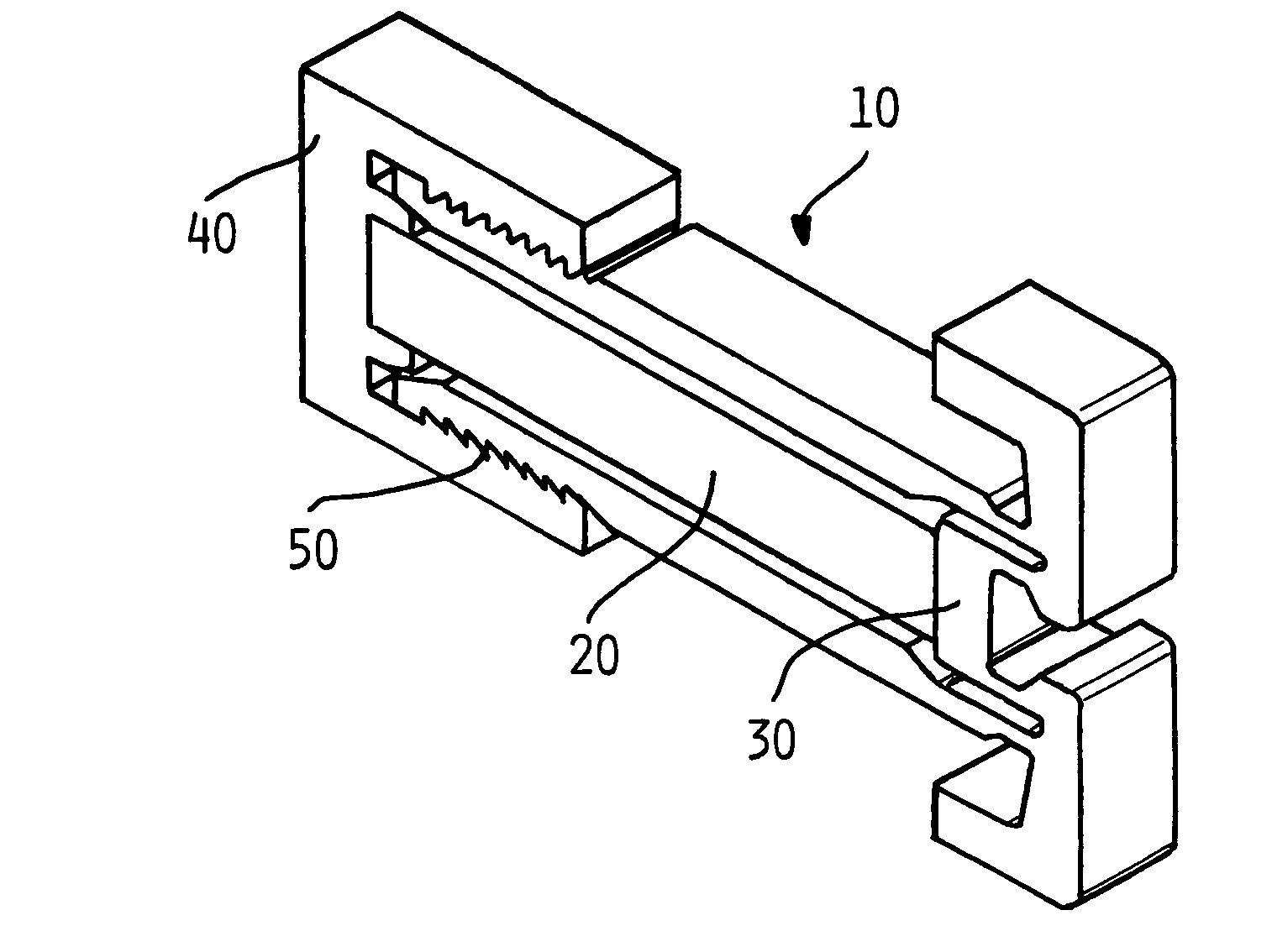
[0029]Now referring to FIG. 5a, the present invention is depicted. Actuator assembly 10 includes a smart material actuator 20, force transfer member 30, floating plate 100, back holding plate 110, and fastener means 110. In this embodiment, the compliant mechanism of the actuator assembly 10 is held together by the back holding plate 120 with two fasteners 110 trapping the smart material actuator 20 between the force transfer member 30 and floating plate 100 causing the smart material actuator 20 to be pre-loaded by the relationship of the back holding plate 120 to the force transfer member 30 and its compliant structure.

[0030]Now referring to FIG. 5b, a close-up view of the floating plate 100 is depicted. As the two fasteners 110 are engaged, back plate 110 will not move in a parallel fashion to the force transfer member 30. The smart material actuator 20 does not tolerate misalignment well. Misalignment can cause a failure of the smart material actuator 20 during assembly. Floatin...

third embodiment

[0031]Now referring to FIG. 6a, the present invention is depicted. Actuator assembly 10 includes a smart material actuator 20, force transfer member 30, rigid back plate 40, lower cam block 210, upper cam block 220, and adjustable cam 210. In this embodiment, the compliant mechanism of the actuator assembly 10 is of a single one-piece design, with two main features including the rigid rear support 40 and force transfer member 30. A second subassembly including the cam block assembly 200, 210, 220 is designed as an adjustable spacer. The smart material actuator 20 is captured between the cam block assembly 200, 210, 220 and force transfer member 30. The cam block assembly 200, 210, 220 is supported by the rigid rear support 40. As the adjustment cam 210 is moved the dimensions of the adjustable spacer change, creating greater or less pre-load.

[0032]Now referring to FIG. 6b, an exploded view of the cam block assembly of FIG. 6a of the present invention is depicted. The lower cam block...

fourth embodiment

[0033]Now referring to FIG. 7a, a cutaway view of the present invention is depicted. The actuator assembly 10 is shown cut at about the midpoint, such that the internal features are visible. Actuator assembly 10 includes a smart material actuator 20, force transfer member 30, rigid back support 40, lower wedge 300, upper wedge 310, and floating plate 100. In this embodiment, the compliant mechanism of the actuator assembly 10 is of a single one-piece design, with two main features including the rigid rear support 40 and force transfer member 30. A second subassembly including the wedge block assembly 300, 310 is designed as an adjustable spacer. The smart material actuator 20 is captured between the wedge block assembly 300, 310 and floating plate 100. The wedge block assembly 300, 310 is supported by the rigid rear support 40. As the wedge assembly 300, 310 is moved with respect to one another the dimensions of the adjustable spacer change, creating greater or less pre-load. The sm...


PUM


Abstract

An apparatus and process for pre-loading an electrically stimulated smart material actuator product to obtain maximum work from the actuator. When a smart material actuator is optimally pre-loaded certain desirable characteristics become apparent, such as work, operational frequency, hysteresis, repeatability, and overall accuracy. When used in conjunction with a mechanically leveraged actuator structure the smart material actuator can be used to its greatest potential. Since the mechanically leveraged actuator can be based on the maximum work provided by the smart material actuator, certain attributes such as the force, and displacement of total system can be adjusted without loss to system efficiency. Pre-loading methods and a determination of the optimal pre-load force are disclosed. Each smart material actuator type has a unique work curve. In the design of an actuator assembly, the process of optimizing uses the unique work curve to optimize the design for the requirements of the particular application. The unique work curve is used by finding the place where the smart material actuator is capable of providing the most work in order to set the optimum pre-load point accordingly. Different mechanical pre-load techniques are provided.

Description

CROSS-REFERENCE TO RELATED APPLICATIONS[0001]This application claims the benefit of provisional patent application Ser. No. 60 / 460,548 filed on Apr. 4, 2003, which is incorporated by reference herein in its entirety.FIELD OF THE INVENTION[0002]The present invention relates generally to an actuator assembly, and more specifically relates to optimization of work from a support structure moveable in response to electrical activation of a smart material actuator.BACKGROUND OF THE INVENTION[0003]The invention is based on actuator technologies being developed for a wide range of applications including industry. One component used in this type of actuator is an electrically stimulated smart material actuator. These smart material actuators when electrically stimulated change shape. This shape change can be designed such that one axis predominantly changes. As this axis changes dimension it is magnified by a lever integral to the main support structure creating an actuator with a useful amo...

Claims


Application Information

Patent Timeline
Patent Type & Authority Patents(United States)
IPC IPC(8): H01L41/08H01L41/04H01L41/053H01L41/09H01L41/18H02N2/00
CPCH02N2/043H01L41/0536H10N30/886H10N30/80H10N30/88
Inventor MOLER, JEFFBUGEL, JOHNTHORNHILL, KEITH A.OUDSHOORN, MARK P.
Owner PARKER INTANGIBLES LLC
Why Eureka
Try Eureka