Contact switching mechanism and electromagnetic relay

Active Publication Date: 2013-05-09
ORMON CORP
View PDF2 Cites 11 Cited by
  • Summary
  • Abstract
  • Description
  • Claims
  • Application Information

AI Technical Summary

Benefits of technology

[0016]According to the present embodiments, at least one of contact pieces is provided with an extension which extends to a contact provided for the remaini

Problems solved by technology

For such a reason, there are problems in that the structure of a conventional contact switching mechanism is complicated and the cost of a conventional contact switching mec

Method used


Image

  • Contact switching mechanism and electromagnetic relay
  • Contact switching mechanism and electromagnetic relay
  • Contact switching mechanism and electromagnetic relay

Examples


case 5

1-5. Case 5

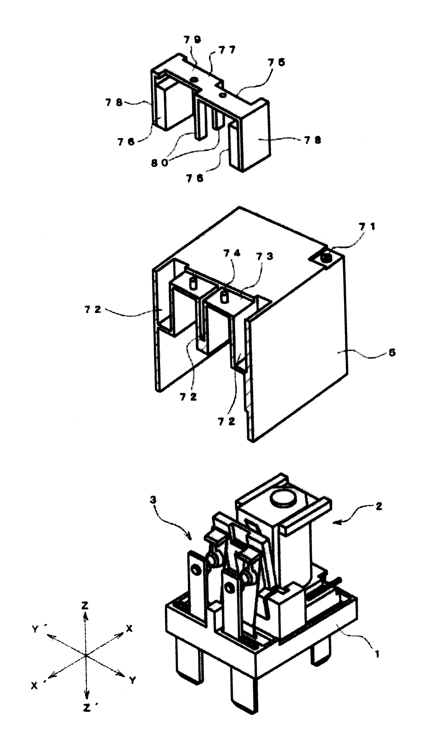
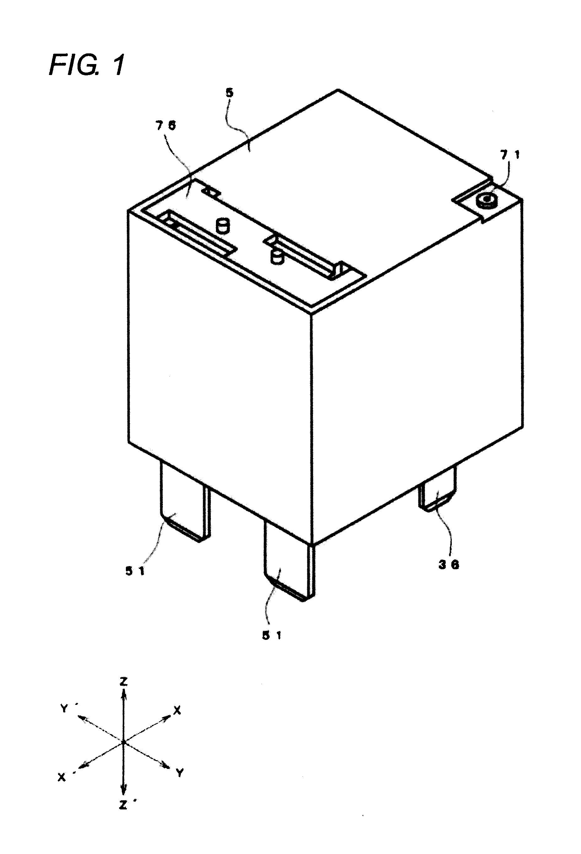
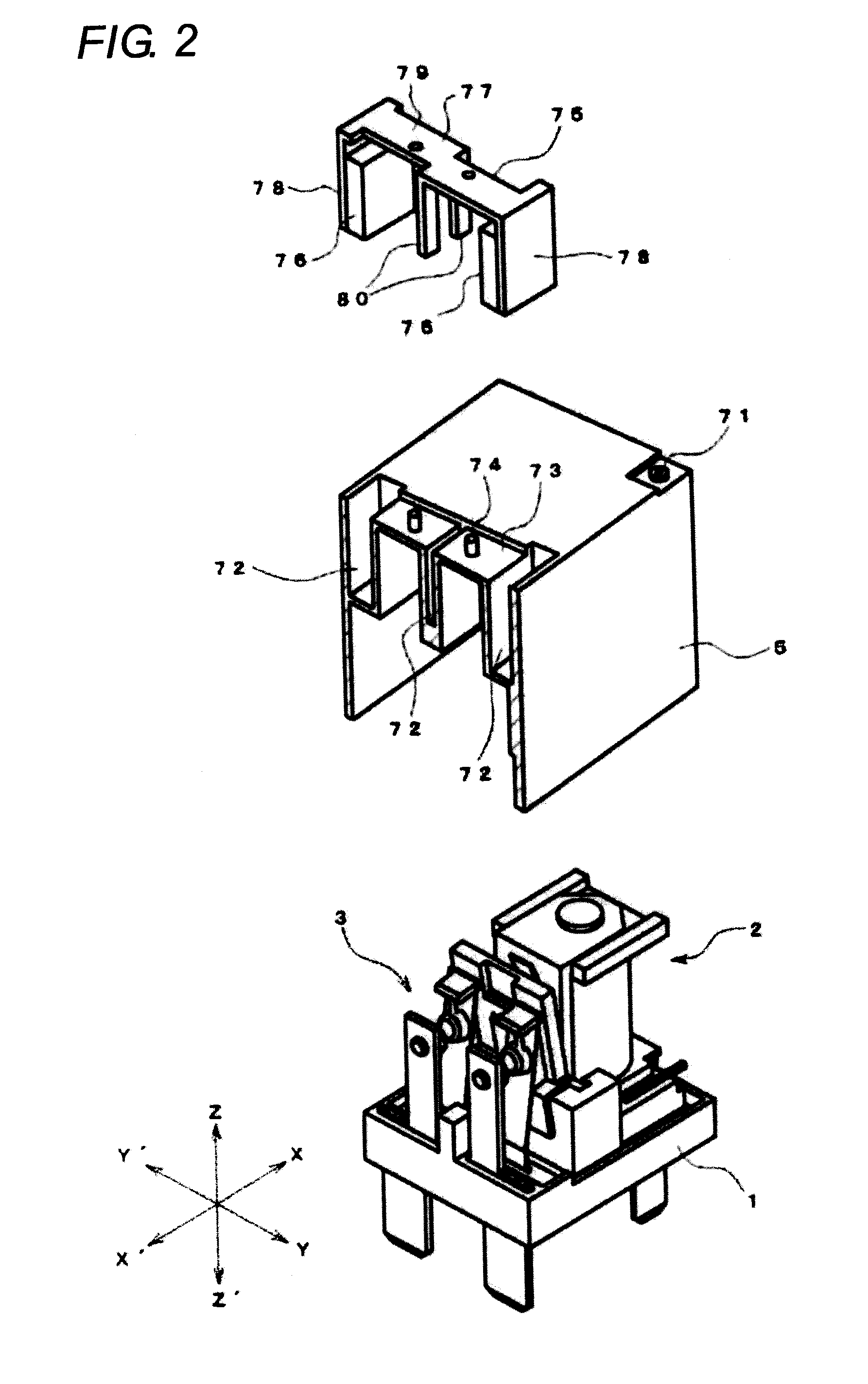
[0056]The case 5 has a box shape which is open at a lower end as shown in FIG. 2 and is made of a synthetic resin material. The case 5 has a sealing hole 71 in a corner of an upper surface. After a fitting portion of the base 1 and the case 5 is sealed, the sealing hole 71 is closed by heat sealing. At an edge of the upper surface of the case 5 on the opposite side of the sealing hole 71, slit-like concave portions 72 are formed at both side portions and a center portion, respectively. A recess 73 that is recessed from the upper surface of the case 5 is formed every between the concave portions 72, and a projection 74 is formed at a center portion of the surface of the recess 73.

[0057]An arc-extinguishing member 75 is attached to the case 5 using the concave portions 72 and the recess 73.

[0058]The arc-extinguishing member 75 includes a pair of permanent magnets 76, arranged at a predetermined interval, for extinguishing the arc and a joint member 77, made of a magnetic ma...


PUM


Abstract

To promptly extinguish an arc generated between contacts with a simple and inexpensive structure without negatively influencing the spring property of a movable contact piece. A contact switching mechanism includes a fixed contact piece with a fixed contact and a movable contact piece with a movable contact which faces the fixed contact in a contactable manner. At least either one of the contact pieces is provided with an extension which extends toward the contact of the remaining contact piece.

Description

TECHNICAL FIELD[0001]The present embodiments relate to a contact switching mechanism and an electromagnetic relay including a contact switching mechanism, and more particularly to a power relay.BACKGROUND ART[0002]Conventionally, there is a known contact switching mechanism where a projection piece for terminating extension of an arc is formed at either one side end, out of a left side end and a right side end, of a leaf spring provided with a movable contact (for example, refer to Japanese Unexamined Patent Publication No. 2006-196372).[0003]However, in the conventional contact switching mechanism, the arc generated between contacts is extended by the action of magnetic force and is terminated by the projection piece, where the position of the projection piece from the contacts is farther than a distance between the contacts. For this reason, there is a concern that the position of termination is not coincident with that of the projection piece when the arc actually occurs.[0004]An...

Claims


Application Information

Patent Timeline
IPC IPC(8): H01H33/18H01H50/54
CPCH01H1/2066H01H50/26H01H9/46H01H9/443H01H50/38H01H50/56
Inventor KAKIMOTO, TOSHIYUKISHINKAI, TETSUOMASUI, YASUYUKIYAMASHITA, TSUKASA
Owner ORMON CORP
Why Eureka
Try Eureka