Accelerated rendering with temporally interleaved details

a technology of temporal interleaved details and rendering, applied in the field of graphic processing, can solve the problems of increasing the computational load of the gpus, affecting so as to achieve the effect of maintaining the perceived image quality of the display and reducing the computational load of the gpu

Active Publication Date: 2013-05-09
NVIDIA CORP
View PDF10 Cites 115 Cited by
  • Summary
  • Abstract
  • Description
  • Claims
  • Application Information

AI Technical Summary

Benefits of technology

[0010]One advantage of the disclosed method is that rendering complementary reduced resolution frames in conjunction with interleaving the display frames corresponding to the complementary reduced resolution frames can lower the computational load on the GPU while maintaining the perceived image quality of the display.

Problems solved by technology

For example, rendering a display image having a resolution of 1280×1024 pixels is substantially more computationally expensive than rendering a display image having a resolution of 800×600 pixels.
For example, rendering display images for a display device having a display frequency of 120 Hz (120 frames / second) is substantially more computationally expensive than rendering display images for a display device having a display frequency of 60 Hz (60 frames / second).
As the foregoing illustrates, as the demand for rendering display images at higher resolutions and / or at higher display frequencies increases, the computational loads on the GPUs increase as well.
A consequence of increasing the computational load on a GPU with respect to rendering operations is that a larger number of GPU cycles are continuously consumed by those operations.
The GPU is thus not able to effectively perform other graphics or offloaded numerical computations.
Further, in some instances, because of a lack of computational power, the GPU may not be able to support high-resolution processing or a high display frequency.

Method used


Image

  • Accelerated rendering with temporally interleaved details
  • Accelerated rendering with temporally interleaved details
  • Accelerated rendering with temporally interleaved details

Examples


Embodiment Construction

[0018]In the following description, numerous specific details are set forth to provide a more thorough understanding of the present invention. However, it will be apparent to one of skill in the art that the present invention may be practiced without one or more of these specific details. In other instances, well-known features have not been described in order to avoid obscuring the present invention.

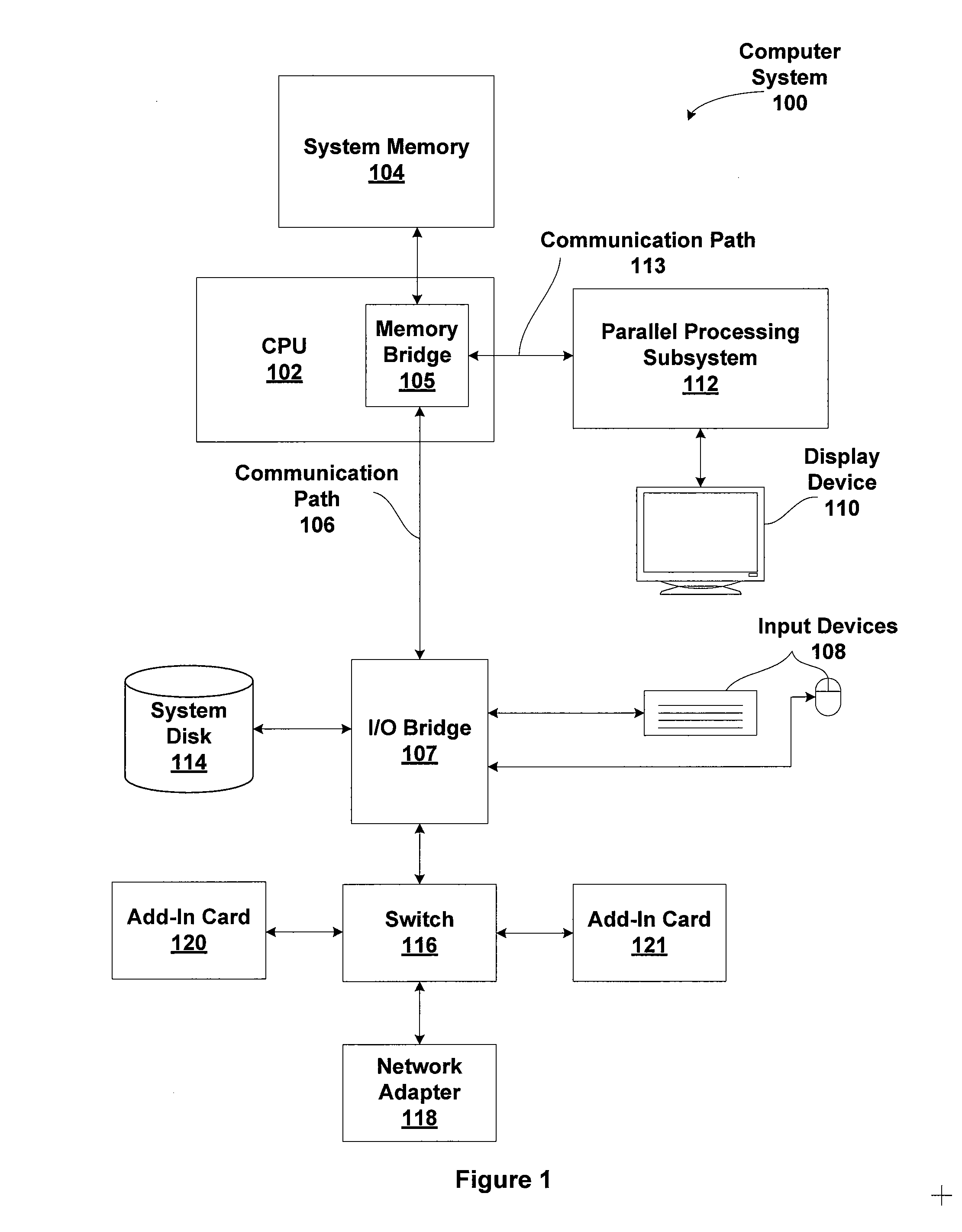
[0019]FIG. 1 is a block diagram illustrating a computer system 100 configured to implement one or more aspects of the present invention. As shown, computer system 100 includes a central processing unit (CPU) 102 and a system memory 104 communicating via a bus path through a memory bridge 105. Memory bridge 105 may be integrated into CPU 102 as also shown, or alternatively, memory bridge 105, may be a conventional device, e.g., a Northbridge chip, that is connected via a bus to CPU 102. Memory bridge 105 is connected via communication path 106 (e.g., a HyperTransport link) to an I / O (inp...


PUM


Abstract

One embodiment of the invention sets forth a mechanism for interleaving consecutive display frames rendered at complementary reduced resolutions. The GPU driver configures a command stream associated with a frame received from a graphics application for reduced frame rendering. The command stream specifies a nominal resolution at which the frame should be rendered. The reduced resolution associated with the frame is determined based on the reduced resolution of an immediately preceding frame (i.e., the complementary reduced resolution), if one exists, or on GPU configuration information. The GPU driver then modifies the command stream to specify the reduced resolution. The GPU driver also inserts an upscale command sequence specifying the nominal resolution into the command stream. Once the command stream is configured in such a manner, the GPU driver transmits the command stream to the GPU for reduced rendering.

Description

CROSS-REFERENCE TO RELATED APPLICATIONS[0001]This application is a continuation of co-pending U.S. Pat. No. 8,294,714 entitled “ACCELERATED RENDERING WITH TEMPORARILY INTERLEAVED DETAILS”, Ser. No. 12 / 493,101, filed Jun. 26, 2009, hereby incorporated herein by reference.BACKGROUND OF THE INVENTION[0002]1. Field of the Invention[0003]The present invention relates generally to the field of graphics processing, more specifically, to accelerated rendering with temporally interleaved details.[0004]2. Description of the Related Art[0005]A graphics processing unit (GPU) is a specialized processor that is configured to efficiently process complex graphics and other numerical computations. In typical computing systems, graphics processing and other computationally-intensive operations are off-loaded by the central processing unit (CPU) to the GPU. One task usually offloaded to the GPU is graphics rendering, where the GPU processes a frame of graphics data to render a display image that may t...

Claims


Application Information

Patent Timeline
Patent Type & Authority Applications(United States)
IPC IPC(8): G06T15/00
CPCG06T15/00G06T15/005G09G2360/08G09G5/363G09G2340/0407G06T2210/52
Inventor BAKDASH, JONATHANMO, QILUEBKE, DAVIDVOORHIES, DOUGLAS A.
Owner NVIDIA CORP
Why Eureka
Try Eureka