
Transmission management system and transmission system

Active Publication Date: 2013-05-09
RICOH KK
View PDF8 Cites 37 Cited by
  • Summary
  • Abstract
  • Description
  • Claims
  • Application Information

AI Technical Summary

Benefits of technology

The present invention aims to provide a better transmission system and management system for eliminating problems in the related art. This results in improved efficiency and performance.

Problems solved by technology

However, since the SIP is designed as the communication protocol specifically to control a call or a communication session between the two locations (i.e., two terminals), the SIP may not control calls among more than two locations (i.e., two or more communication terminals).
However, in the related art videoconference system, a management system utilized for controlling communications among videoconferencing terminals may not manage communication statuses of the videoconferencing terminals.
Accordingly, when the management system transmits information desirable for initiating the communications to destination videoconferencing terminals, connections between the videoconferencing terminals may not be established due to engagement of the destination videoconferencing terminals with other videoconference terminals.
That is, in the related art technology, the management system does not detect communication statuses of the destination videoconference terminals before transmitting the information desirable for initiating the communications to destination videoconference terminals, and therefore, the management system may not effectively control the connections among the videoconference terminals.

Method used


Image

  • Transmission management system and transmission system
  • Transmission management system and transmission system
  • Transmission management system and transmission system

Examples


Embodiment Construction

[Overall Configuration of Embodiment]

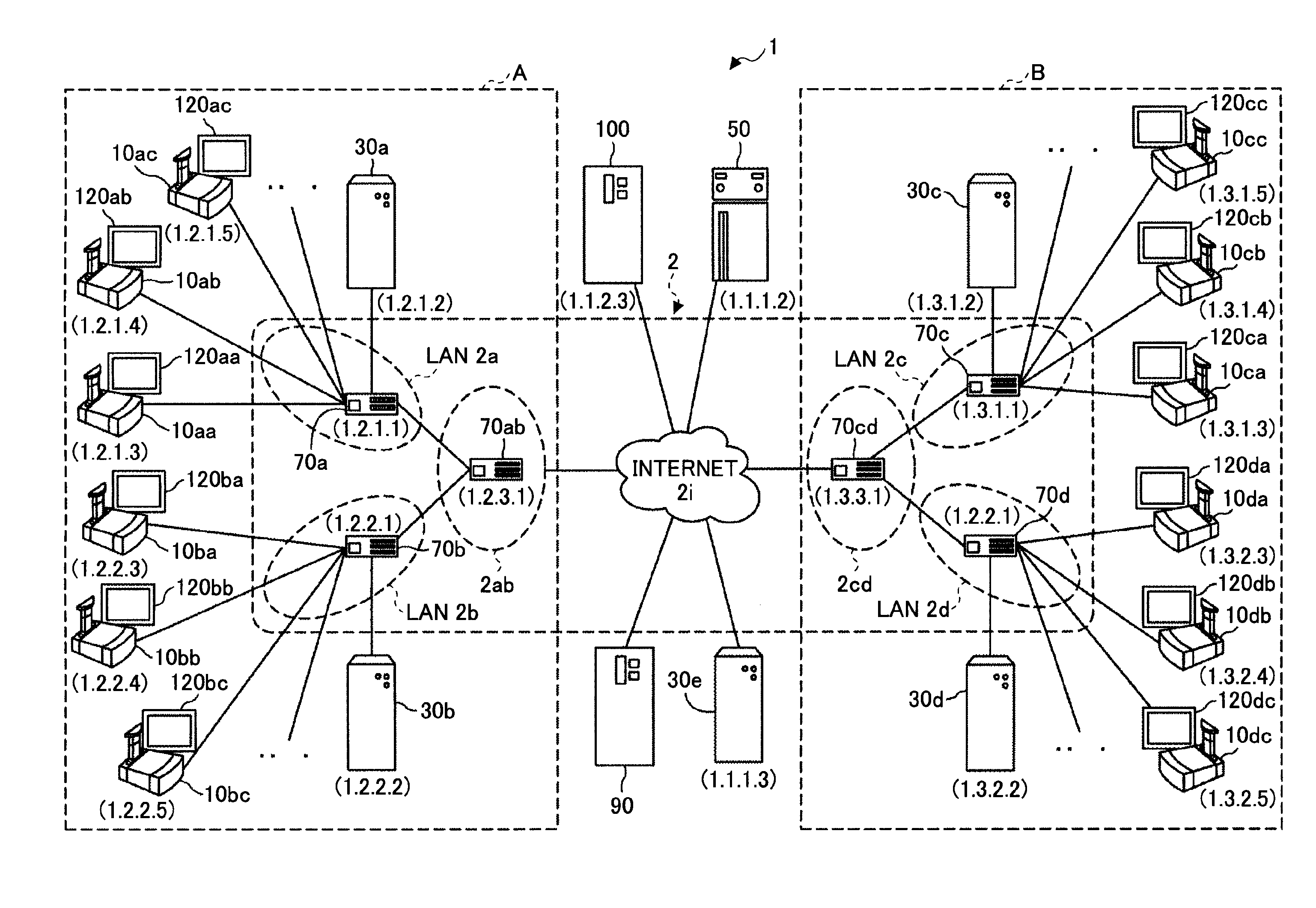
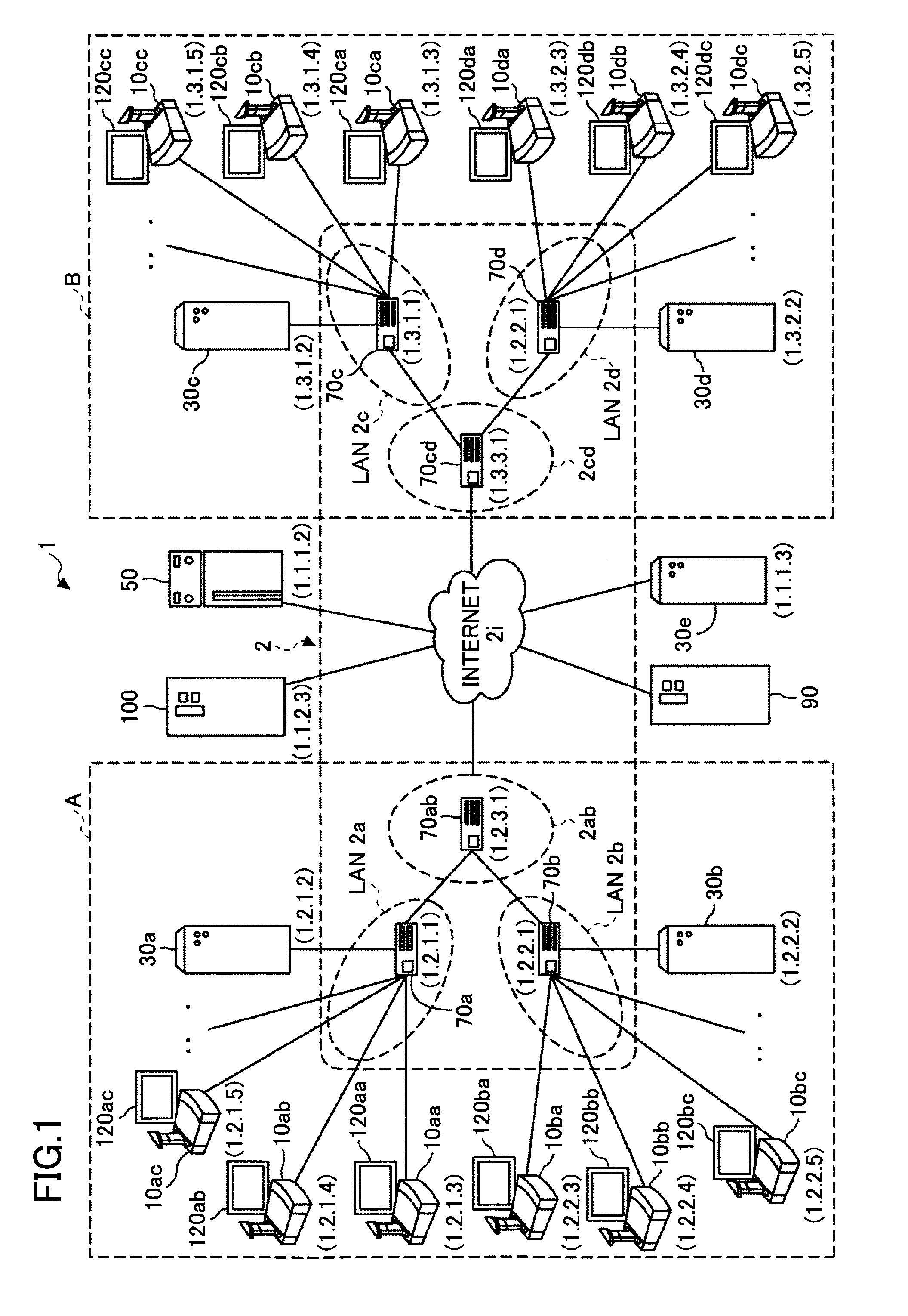
[0047]In the following, preferred embodiments will be described with reference to FIGS. 1 through 37. FIG. 1 is a schematic diagram illustrating a transmission system 1 according to an embodiment. Initially, an outline of the transmission system 1 according to the embodiment is described with reference to FIG. 1.

[0048]There are various types of transmission systems. One example may be a data providing system. In the data providing system, content data are transmitted from one terminal to another terminal via a transmission management system in one-way direction. Another example may be a communication system. In the communication system, information or emotional expressions are mutually communicated among two or more transmission terminals via the transmission management system. The communication system is utilized for mutually exchanging information or emotional expressions among the two or more communication terminals (i.e., the transmission ter...


PUM


Abstract

A disclosed transmission management system includes a receiver unit to receive alteration information for altering a communication status of a first transmission terminal from the first transmission terminal that communicates with a second transmission terminal to exchange content data, a terminal management unit to manage first status information indicating the communication status of the first transmission terminal, an acquisition unit to acquire the first status information from the terminal management unit in a case where the receiver unit receives the alteration information for altering the communication status of the first transmission terminal, and an alteration unit to alter the first status information managed by the terminal management unit, based on the alteration information for altering the communication status of the first transmission terminal received by the receiver unit and the first status information acquired by the acquisition unit.

Description

TECHNICAL FIELD[0001]The disclosures herein generally relate to a transmission system to transmit content data and a transmission management system to manage a status of a transmission terminal to transmit the content data.BACKGROUND ART[0002]A videoconferencing system is a technology to conduct videoconferences via communication networks such as the Internet. Owing to recent demand for reducing time and expenses for business trips, such a videoconferencing system is becoming increasingly popular. In the videoconferencing system, the videoconference may be implemented by transmitting and receiving telecommunication data such as image data and audio data between two or more terminals at different locations.[0003]In a case where the two terminals at different locations start communicating, and the communications are conducted via Internet Protocol (IP) telephones (i.e., one of phone services), the Session Initiation Protocol (SIP) is generally utilized as a communication protocol to e...

Claims


Application Information

Patent Timeline
IPC IPC(8): H04L29/06H04N21/258H04N21/442
CPCH04M3/567H04L65/403H04M3/42374H04N7/152H04L65/1083H04W76/14H04W8/22
Inventor UMEHARA, NAOKI
Owner RICOH KK
Learn More