
Electrosurgical forceps with composite material tips

a technology of composite materials and forceps, which is applied in the field of electrosurgical forceps, can solve the problems of requiring the cleaning of the forceps and further bleeding, and achieve the effects of preventing tissue sticking, reducing bleeding, and dissipating heat generated at the tip

Active Publication Date: 2007-11-15
KIRWAN SURGICAL PRODS
View PDF26 Cites 17 Cited by
  • Summary
  • Abstract
  • Description
  • Claims
  • Application Information

AI Technical Summary

Benefits of technology

[0005] Electro-surgical forceps are provided which minimize or prevent sticking to the tissue of a patient and eschar buildup. The forceps include a pair of blade members extending from an insulated cap portion to a tip. At least one of the blade members is electrically conducting. Within the cap portion, the blades are electrically connected to terminals for connection to an electrical generator. At least the tip of the blade member is comprised of a silver / nickel composite material. The silver / nickel composite material is comprised of elongated nickel particles interspersed in a matrix of silver particles. The elongated nickel particles are aligned with each other and with a longitudinal axis of the tip member. The tip is operative to dissipate heat generated at the tip to prevent sticking of tissue to the forceps during use and to allow operation of the forceps at a lower power level. In one embodiment, a blade member includes a body or handle of a material such as stainless steel and a tip member comprised of the silver / nickel composite material. In another embodiment, the entire blade member is comprised of the silver / nickel composite material.
[0006] Forceps incorporating a tip comprised of the silver / nickel composite material are simple to manufacture. The tip is formed from a single solid piece of material, which eliminates problems with coatings and platings that may be prone to wear or delamination. The silver / nickel composite material is slightly softer than steel but substantially harder than pure silver, resulting in a tip that is durable without the need for additional work hardening required with pure silver.

Problems solved by technology

If sticking occurs, the surgeon must pull on the forceps to release it from the tissue, possibly causing further bleeding and requiring that the forceps be cleaned.

Method used


Image

  • Electrosurgical forceps with composite material tips
  • Electrosurgical forceps with composite material tips
  • Electrosurgical forceps with composite material tips

Examples


Embodiment Construction

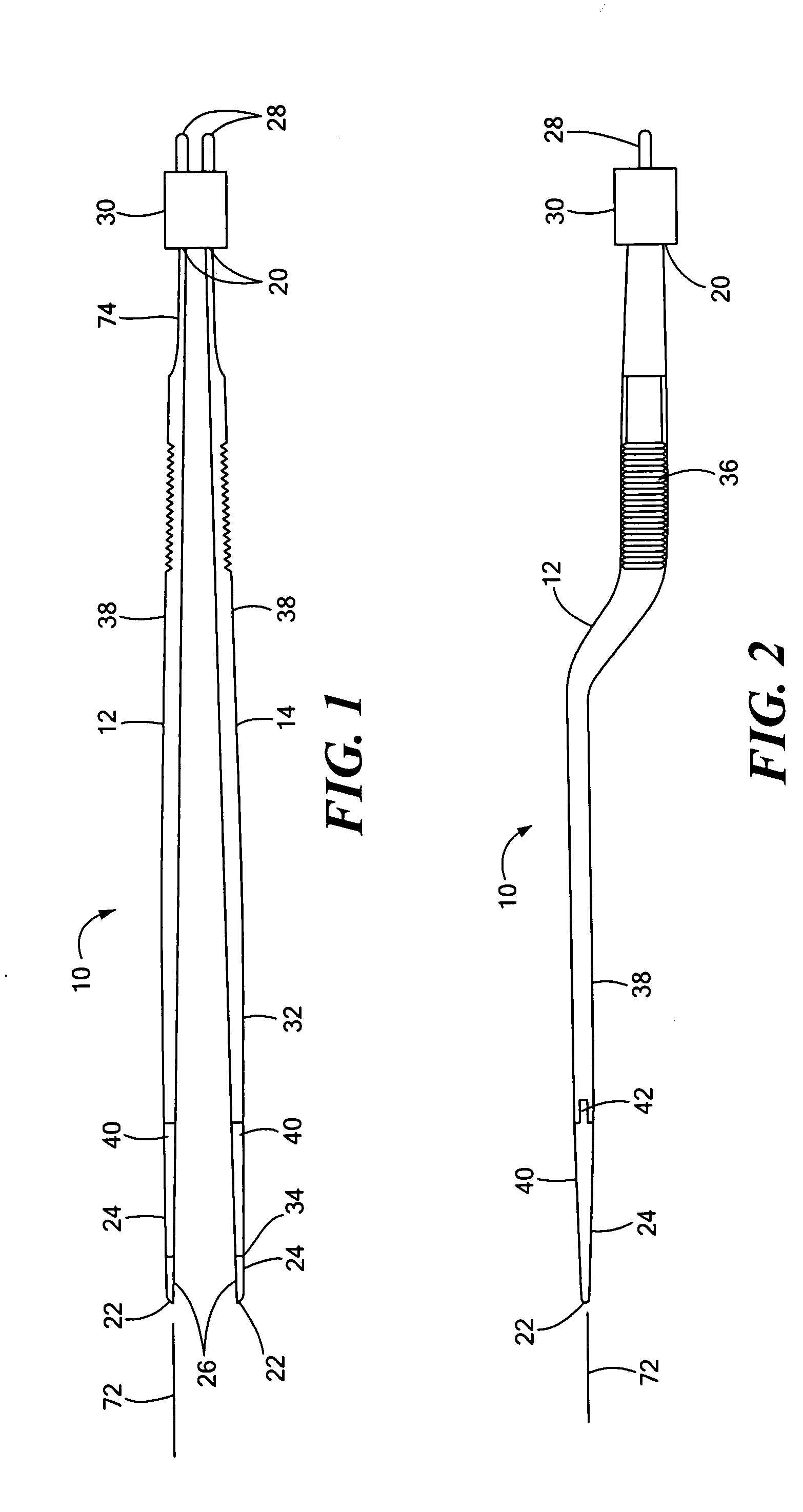
[0015] Referring to FIGS. 1 and 2, a bipolar forceps 10 has first and second blade or electrode members 12 and 14. Each of the blade members is elongated and extends from a first end 20 to a second end 22 at a tip 24. The blade members are generally flat, and the tips are configured for gripping tissue between opposed surfaces 26. The first ends 20 are electrically connected in any suitable manner, such as by crimping, welding, or soldering, to terminal pins 28. First ends 20 along with the terminal pins 24 are encapsulated using an epoxy based material or otherwise mounted within an insulating cap portion 30. The blade members may be insulated with an insulating material 32 along most of their length from the cap portion 30 to a location 34 close to the tip. Alternatively, the blade members may be uninsulated. Serrated finger grips 36 may be formed in each blade member to aid the physician in gripping the forceps during use. A plating of an electrically and thermally conductive bio...


PUM

PropertyMeasurementUnit
Percent by massaaaaaaaaaa

Abstract

An electrosurgical forceps has at least the tip of one blade member formed of a composite material having aligned elongated particles of nickel interspersed in a matrix of silver particles. The tip can be provided as a tip member attached, such as by brazing, to the body of the blade member, or the entire blade member can be formed of the silver / nickel composite material. In another embodiment, the tip or blade member is formed of a dispersion strengthened silver or copper composite material.

Description

CROSS REFERENCE TO RELATED APPLICATIONS [0001] N / A STATEMENT REGARDING FEDERALLY SPONSORED RESEARCH OR DEVELOPMENT [0002] N / A BACKGROUND OF THE INVENTION [0003] Electro-surgical forceps have a pair of resilient blades or arms that are used for grasping and coagulating tissue. The forceps may be monopolar or bipolar. In monopolar forceps, the blades are welded or otherwise joined to form an electrode in electrical communication with an electrical generator. Current flows from the active electrode through the patient's tissue to a dispersive electrode in contact with the patient's skin (which may be at some distance from the forceps) and back to the generator. In bipolar forceps, each blade of the pair comprises an electrode in communication with an electrical generator. Current flows from one blade through the tissue to the other blade. [0004] In some instances, tissue may adhere or stick to the tips of the blades. If sticking occurs, the surgeon must pull on the forceps to release i...

Claims


Application Information

Patent Timeline
IPC IPC(8): A61B18/14
CPCA61B18/1442A61B2018/00148A61B2018/1412A61B2018/1462Y10T29/49208Y10T29/49204Y10T29/49169Y10T29/49117Y10T29/49174
Inventor ARIOLA, JOHN P. JR.KIRWAN, LAWRENCE T.
Owner KIRWAN SURGICAL PRODS
Learn More