
Work area monitor

a work area and monitor technology, applied in the field of work area monitors, can solve the problems of mine workers not equipped with knowledge or tools to understand, mine workers are exposed to a number of major hazards, and the ssr is not ideal for all situations, so as to achieve a much faster scan rate and high error stack

Active Publication Date: 2013-05-16
GROUNDPROBE
View PDF37 Cites 9 Cited by
  • Summary
  • Abstract
  • Description
  • Claims
  • Application Information

AI Technical Summary

Benefits of technology

The Work Area Monitor is a device that uses a radar to measure the slope of the ground and a camera to capture images of the area. When the radar detects movement, the camera can capture the movement visually. This makes it easier to identify and locate any movement in the work area. The system can also detect and measure objects in the work area. The device is suitable for use in low light conditions and has a short range of about -30 m to -200 m. This is shorter than the typical range of an SSR (about -1000 m or more) but allows for quicker detection and localization of alarms. The system can be used to improve safety and efficiency in construction and mining activities.

Problems solved by technology

Nonetheless, the SSR is not ideal for all situations.
Mine workers are exposed to a number of major hazards including sudden or unexpected movement of ground in their immediate work area.
Mine workers are not equipped with the knowledge or tools to understand whether a wall that they are planning to work under is and remains safe.
However there are specific work areas in a mine that are not adequately covered or alarmed by SSR.

Method used


Image

  • Work area monitor
  • Work area monitor
  • Work area monitor

Examples


Embodiment Construction

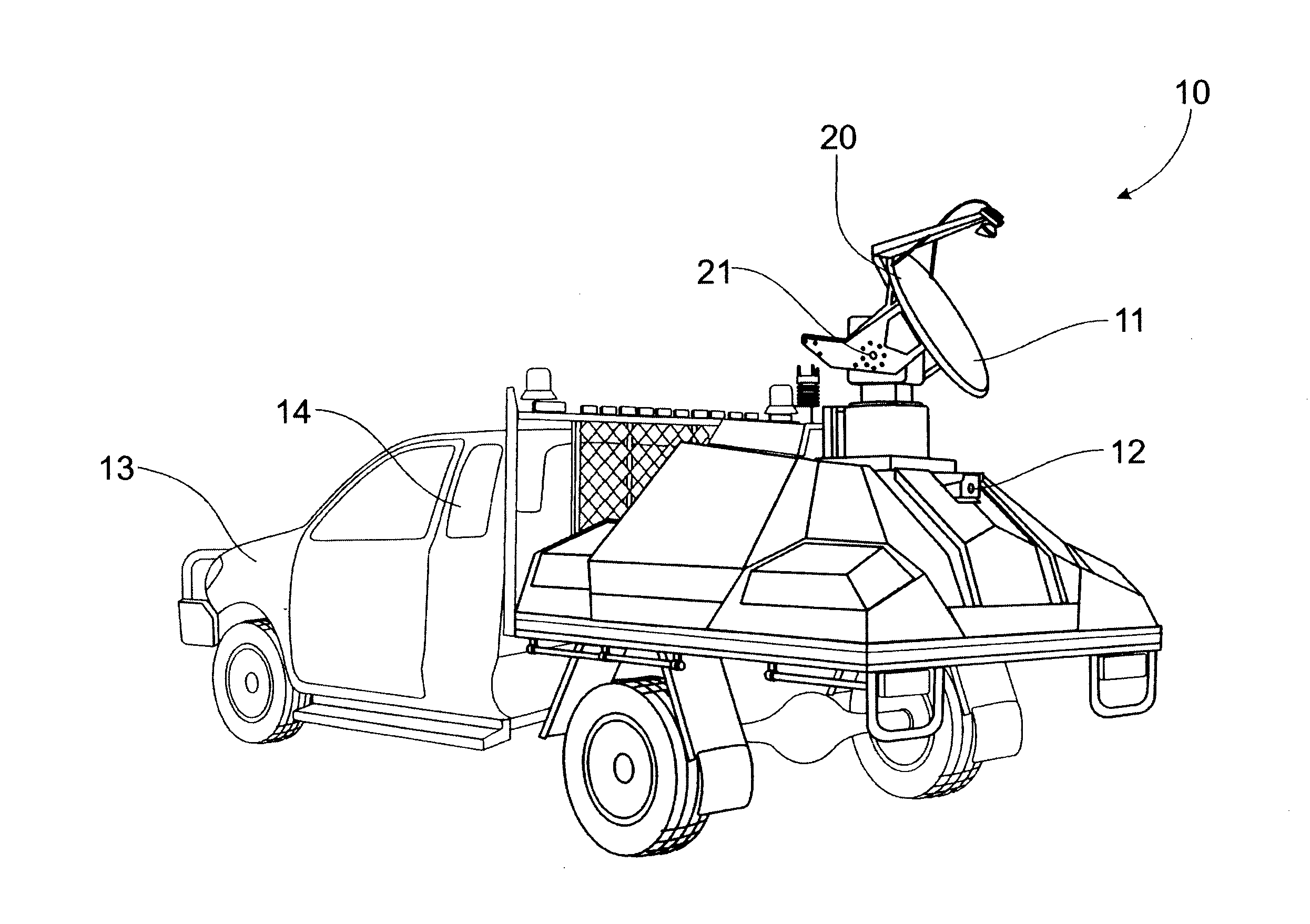
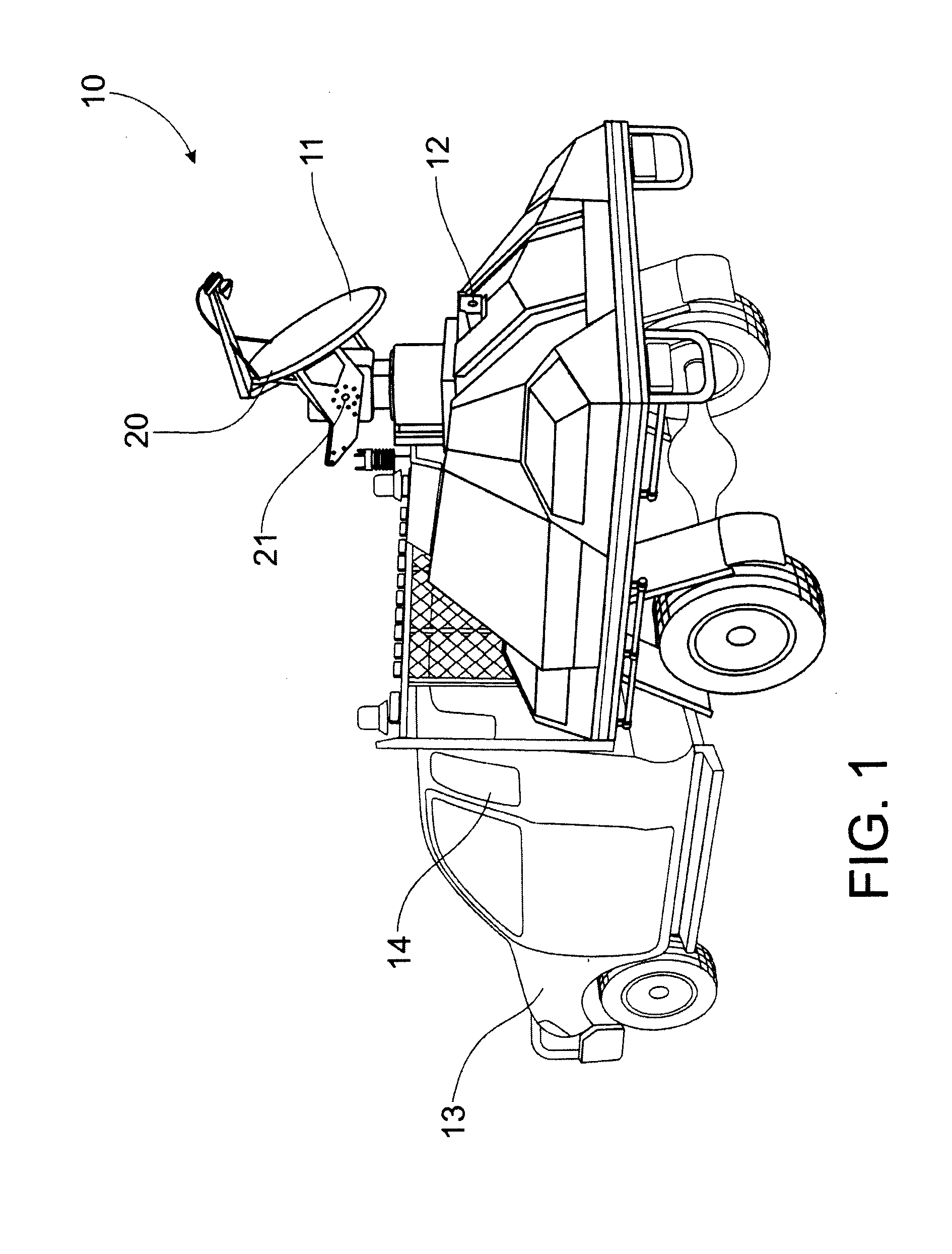
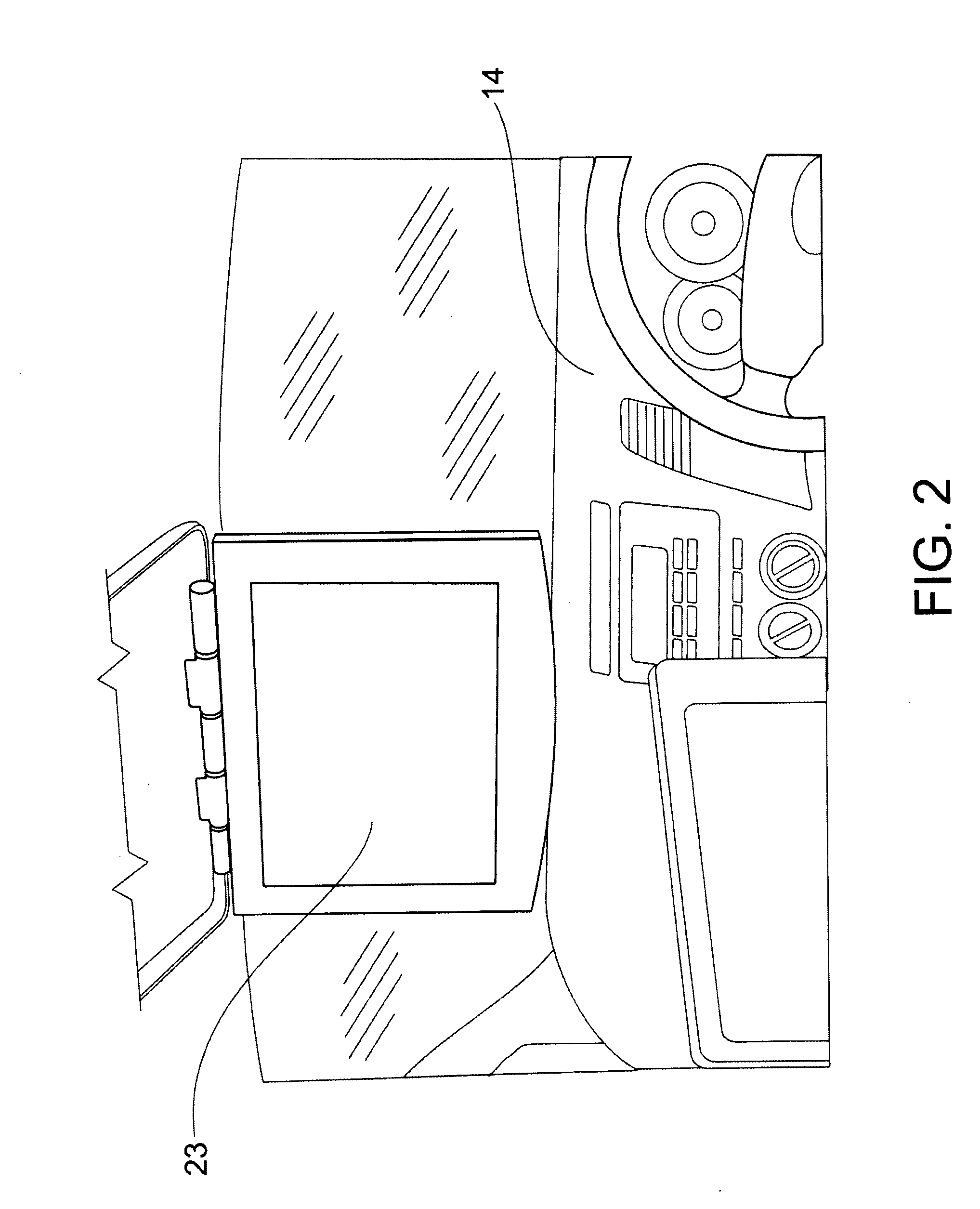
[0045]Embodiments of the present invention reside primarily in a Work Area Monitor providing a visual image of a slope near a work area overlaid with a movement map obtained from interferometrically analysed radar data. The Work Area Monitor is mounted on a motor vehicle for easy mobility, comfortable user setup and reliable power source. The elements of the Work Area Monitor have been illustrated in concise schematic form in the attached drawings, showing only those specific details that are necessary for understanding the embodiments of the present invention, but so as not to obscure the disclosure with excessive detail that will be readily apparent to those of ordinary skill in the art having the benefit of the present description.

[0046]In this specification, adjectives such as first and second, left and right, and the like may be used solely to distinguish one element or action from another element or action without necessarily requiring or implying any actual such relationship ...


PUM


Abstract

A Work Area Monitor comprising a radar module mounted on a motorised vehicle. The Work Area Monitor provides early warning of slope failure in a work area by generating an alarm if movement detected in movement data derived from interferometrically processed radar images exceeds a threshold.

Description

FIELD OF THE INVENTION[0001]This invention relates to a work area monitor that employs radar to detect movement of a slope and raise an alarm if dangerous movement is detected. The invention is particularly useful for open cut mine sites and civil excavation sites, and potentially useful for underground mines.[0002]BACKGROUND TO THE INVENTION[0003]The use of radar to produce interferometry maps for identifying movement in a slope is known. U.S. Pat. No. 6,850,183 describes a slope monitoring system that consists of a radar module that records radar images of a selected slope and a video module that records visual images of the same slope. A data processor performs coordinate registration to align the radar images and the visual images. Slope movement is detected by interferometry. The invention is embodied in a product produced by GroundProbe Pty Ltd that is referred to as the SSR.[0004]The SSR product has been used very successfully to monitor the stability of large slopes in open-...

Claims


Application Information

Patent Timeline
IPC IPC(8): G01S13/88G01S7/04
CPCG01S7/003G01S7/062G01S13/89G01S13/885G08B27/006G08B27/008G01S7/04G08B7/06
Inventor NOON, DAVIDBELLETT, PATRICK T.
Owner GROUNDPROBE
Learn More