
Video signal processing device and video signal processing method

Inactive Publication Date: 2013-05-16
PANASONIC INTELLECTUAL PROPERTY MANAGEMENT CO LTD
View PDF2 Cites 14 Cited by
  • Summary
  • Abstract
  • Description
  • Claims
  • Application Information

AI Technical Summary

Benefits of technology

The video signal processing device and method described in the patent can accurately locate and correct the quality of additional information that is displayed on a stereo video. This is done by performing 2D to 3D conversion, resulting in a high-quality video that is suitable for viewing on a display. The technical effect of this invention is the ability to accurately control the quality of a stereo video, allowing for improved viewing experiences for users.

Problems solved by technology

This is because such additional information indicates characters or still images obtained, for instance, using computer graphics (CG) in many cases, and thus if quality correction for correcting quality of an image of scenery or a person is performed on such additional information, a viewer is often given a sense of unnaturalness.

Method used


Image

  • Video signal processing device and video signal processing method
  • Video signal processing device and video signal processing method
  • Video signal processing device and video signal processing method

Examples


embodiment 1

Summary of Embodiment 1

[0096]Examples of advantageous effects of the present embodiment are as follows.

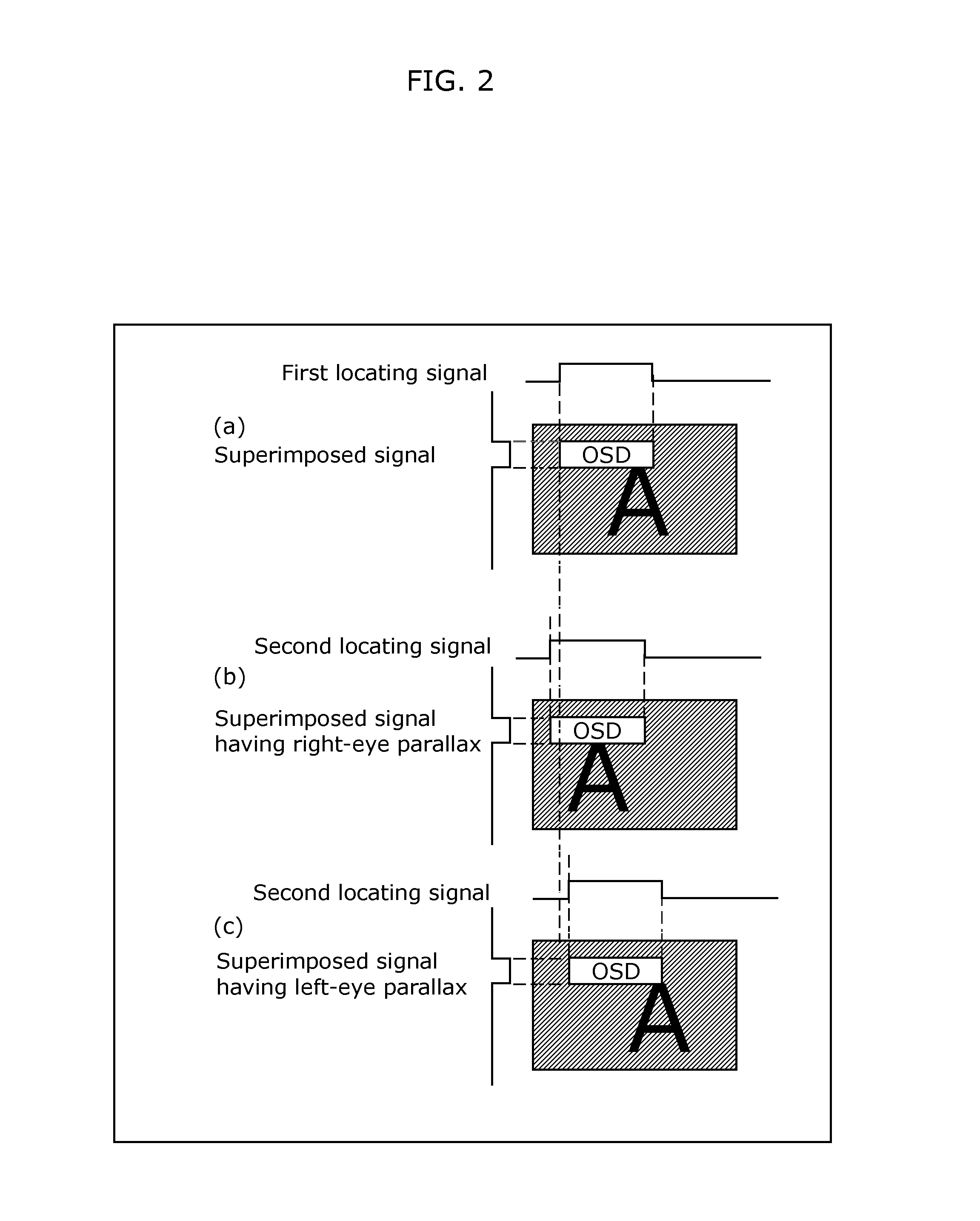
[0097]According to a conventional technique, if a superimposed signal is stereo-converted, superimposed additional information such as OSD is also stereo-converted, and the display position of the additional information also shifts. Accordingly, although there has been an attempt to avoid quality correction only on the display area of the additional information, selectively, it results in a failure.

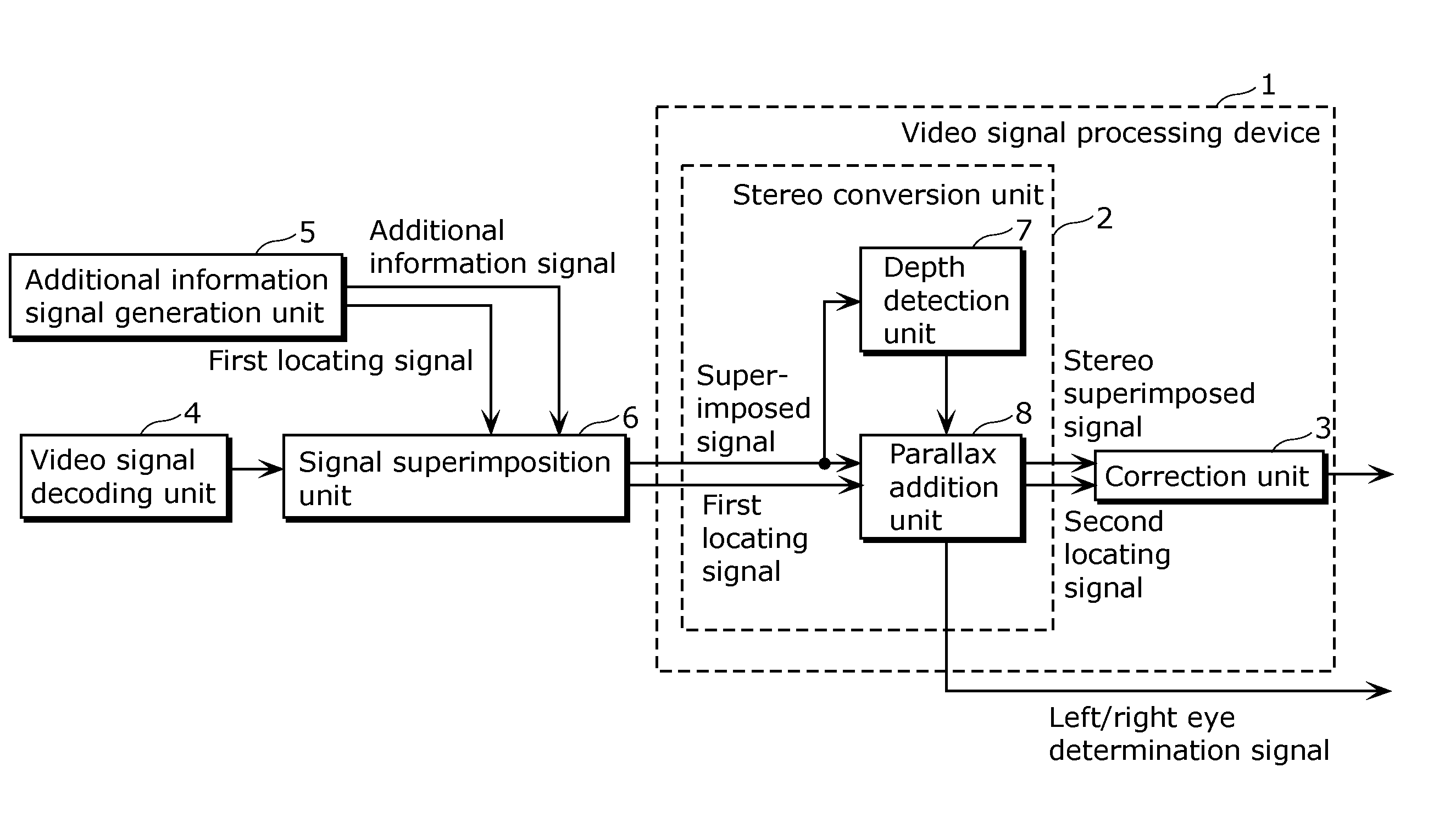
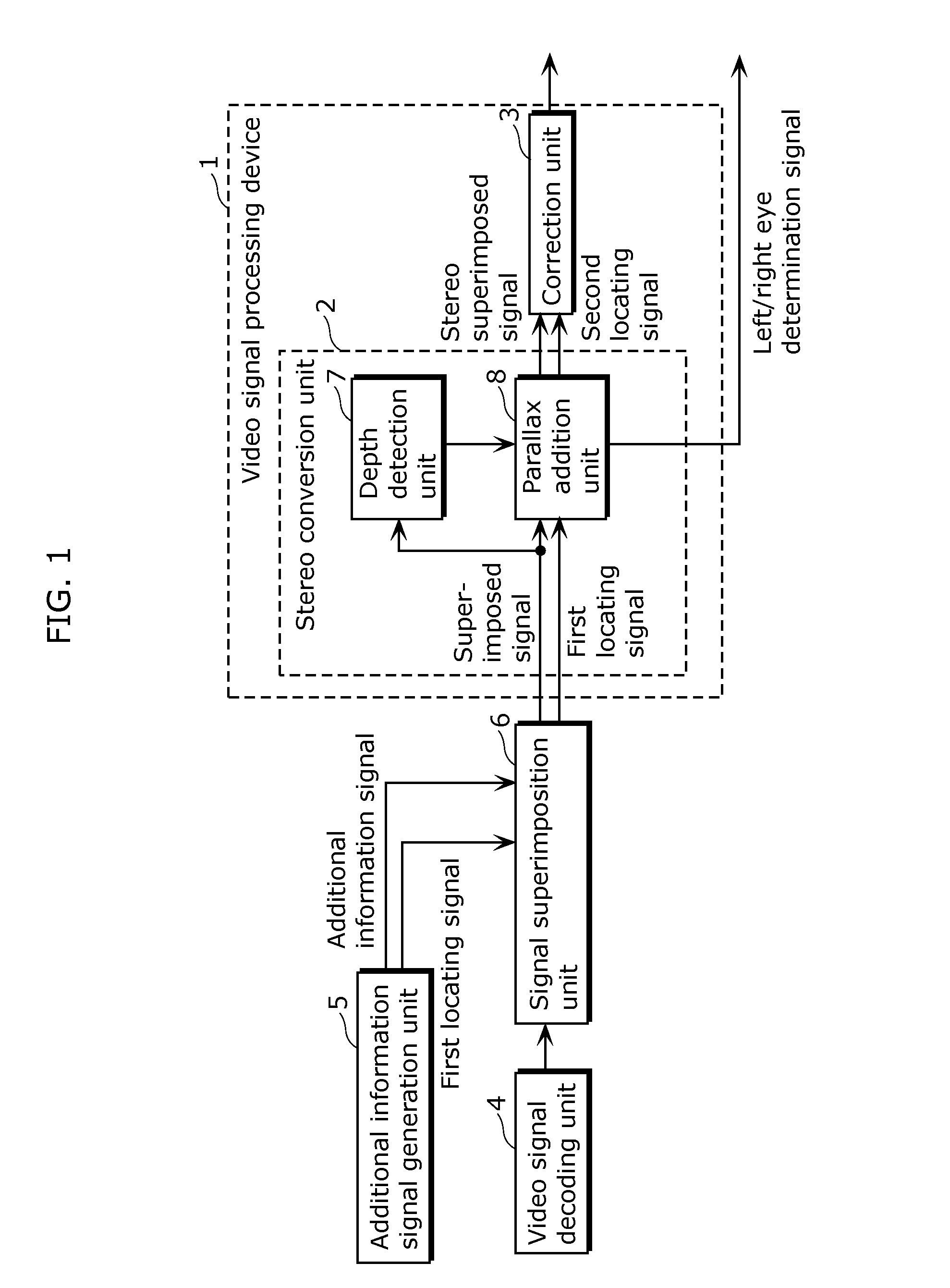
[0098]In contrast, according to the present invention, the stereo conversion unit 2 also corrects first locating signals indicating the position of additional information such as OSD, in accordance with stereo conversion processing on two-dimensional video signals, thereby generating second locating signals as new position information.

[0099]The video signal processing device 1 according to the present embodiment can locate, by using such second locating signals, the position of additiona...

embodiment 2

Summary of Embodiment 2

[0144]Examples of advantageous effects of the present embodiment are as follows.

[0145]First, the present embodiment has an effect of not performing quality correction on an area in which additional information such as OSD is displayed, as with Embodiment 1. Thus, the present embodiment brings an advantage of not giving a viewer a sense of unnaturalness, and the advantage leads to a great effect in light of health and mind, in addition to improvement in the quality of a video outputted from the video signal processing device 10 as a whole, as well as in Embodiment 1.

[0146]Furthermore, an example of a feature of the video signal processing device 10 according to the present embodiment is that the additional information such as OSD is not stereo-converted. It is possible to give a viewer various visual effects by stereo-converting additional information such as OSD. However, it is often difficult to set an appropriate value indicating how much depth is to be give...


PUM


Abstract

A video signal processing device includes: a stereo conversion unit which generates a stereo superimposed signal by performing stereo conversion processing on a superimposed signal obtained by superimposing, on a two-dimensional video signal, an additional information signal indicating additional information to be combined with a two-dimensional video and displayed, and shifts a first locating signal indicating a position of the additional information in the two-dimensional video, according to an amount of shift caused by the stereo conversion processing on the additional information signal, to generate a second locating signal indicating a position of the additional information in a video indicated by the stereo superimposed signal; and a correction unit performs, on the stereo superimposed signal, quality correction for an area other than an area located by the second locating signal.

Description

TECHNICAL FIELD[0001]The present invention relates to a video signal processing device, and in particular to a video signal processing device which converts two-dimensional video signals into stereo video signals.BACKGROUND ART[0002]Currently, most of video display devices typified by television receivers have a function to combine additional information typified by captions, subtitles, and on screen display (OSD), for instance, with video signals to be broadcast or video signals stored in a recording medium, and display the resultant signals.[0003]In general, quality correction that is performed on a video is preferably not performed on additional information combined with the video as mentioned above. This is because such additional information indicates characters or still images obtained, for instance, using computer graphics (CG) in many cases, and thus if quality correction for correcting quality of an image of scenery or a person is performed on such additional information, a...

Claims


Application Information

Patent Timeline
IPC IPC(8): H04N13/00
CPCH04N13/0029H04N13/007H04N13/183H04N13/139
Inventor NIO, YUTAKATERAI, HARUKOKASE, DAISUKE
Owner PANASONIC INTELLECTUAL PROPERTY MANAGEMENT CO LTD
Learn More