
Methods and Apparatus for Blending Images

a technology of blending and images, applied in the field of methods and apparatus for blending images, can solve the problems of complex darkroom techniques, difficult to capture in a single exposure, and combining multiple negatives to produce a single prin

Active Publication Date: 2013-05-16
ADOBE INC
View PDF24 Cites 69 Cited by
  • Summary
  • Abstract
  • Description
  • Claims
  • Application Information

AI Technical Summary

Benefits of technology

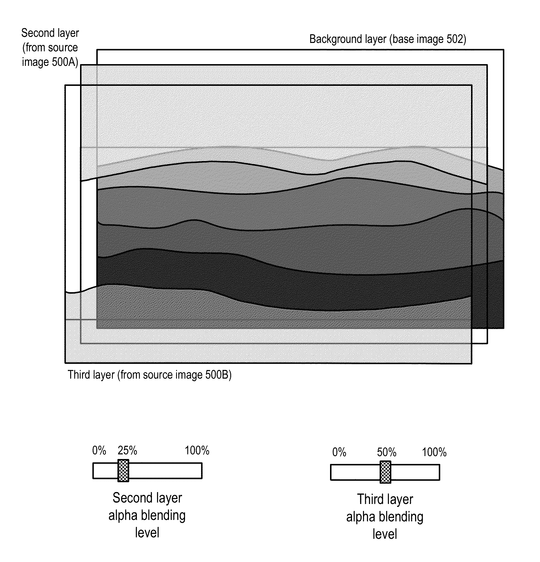
The patent describes methods and apparatus for blending regions from multiple images to create a blended image. The technical effects of the patent include the ability to select specific regions from multiple source images and blend them with a base image using alpha blending, as well as the ability to adjust the blending levels for different regions from the same source image. The patent also describes a method for maintaining a label map to identify all the regions in the blended image that are from the same source image. Overall, the patent provides a way to create more complex and detailed blended images by blending multiple source images with a base image.

Problems solved by technology

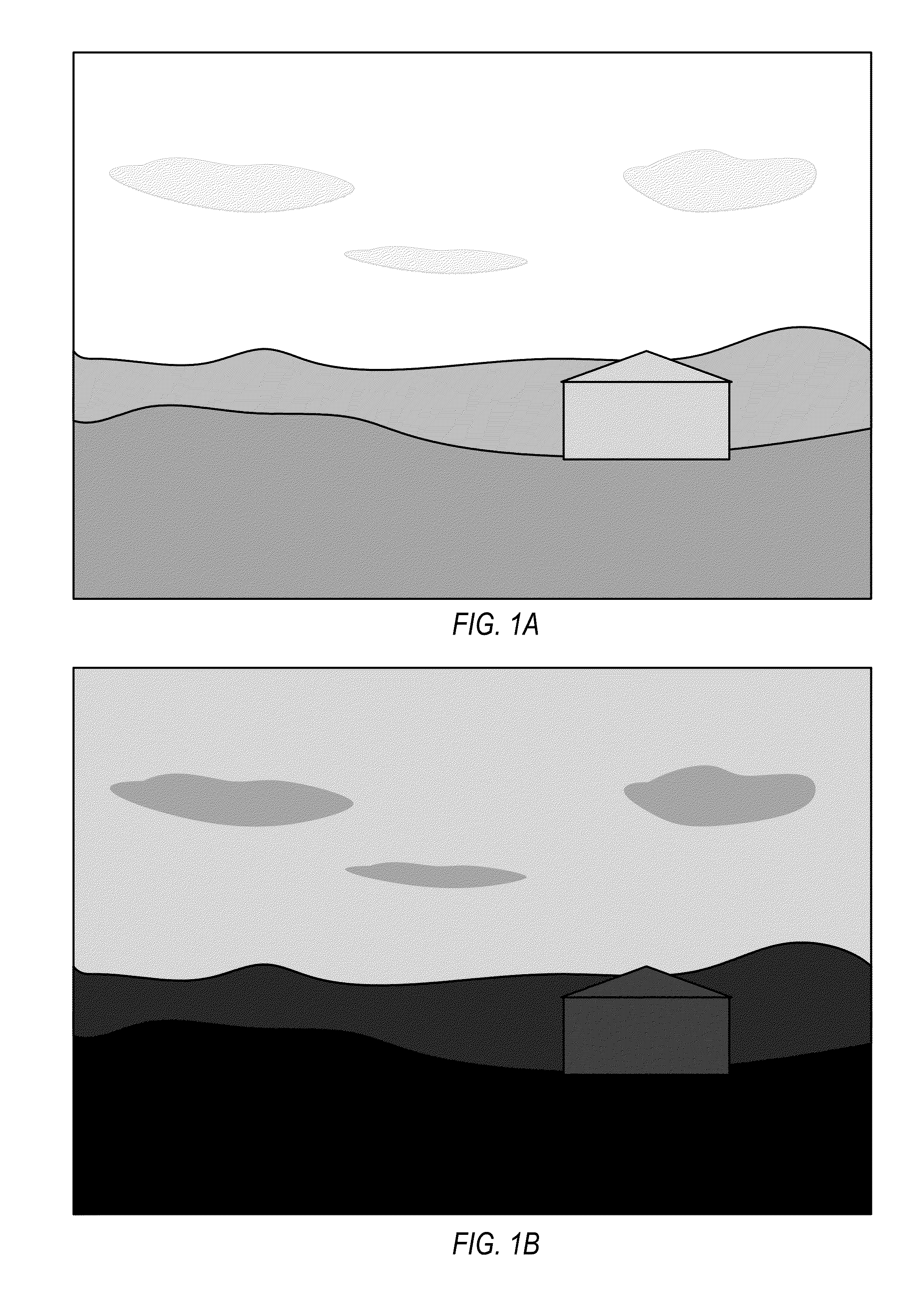
There are many photographic situations where the range of luminosity values spanning shadows and highlights in a scene is large and thus difficult to capture in a single exposure.
In conventional, film-based photography, combining multiple negatives to produce a single print, for example captured at different exposures, requires complicated darkroom techniques.
However, conventional digital image processing techniques for merging images tend to either require the user to manually generate several separate masks that each entirely cover one of the various regions in the multiple images, or are automated and thus do not give the user much if any control over the output.

Method used


Image

  • Methods and Apparatus for Blending Images
  • Methods and Apparatus for Blending Images
  • Methods and Apparatus for Blending Images

Examples


example implementations

[0088]FIG. 14 illustrates an example image blending module 920 that may implement image blending methods and workflows as illustrated in FIGS. 1A through 13. Embodiments of an image blending module 920 may, for example, be implemented as a stand-alone image processing application, as a module of an image processing application, as a plug-in for applications including image processing applications, and / or as a library function or functions that may be called by other applications. Embodiments of image blending module 920 may be implemented in any image processing application, including but not limited to Adobe® PhotoShop® Adobe® PhotoShop® Elements®, and Adobe® After Effects®. FIG. 15 illustrates an example computer system on which embodiments of image blending module 920 may be implemented.

[0089]Image blending module 920 receives as input a set of two or more digital images 910. An example set of input images is shown in FIG. 10A. Image blending module 920 facilitates workflows and ...


PUM


Abstract

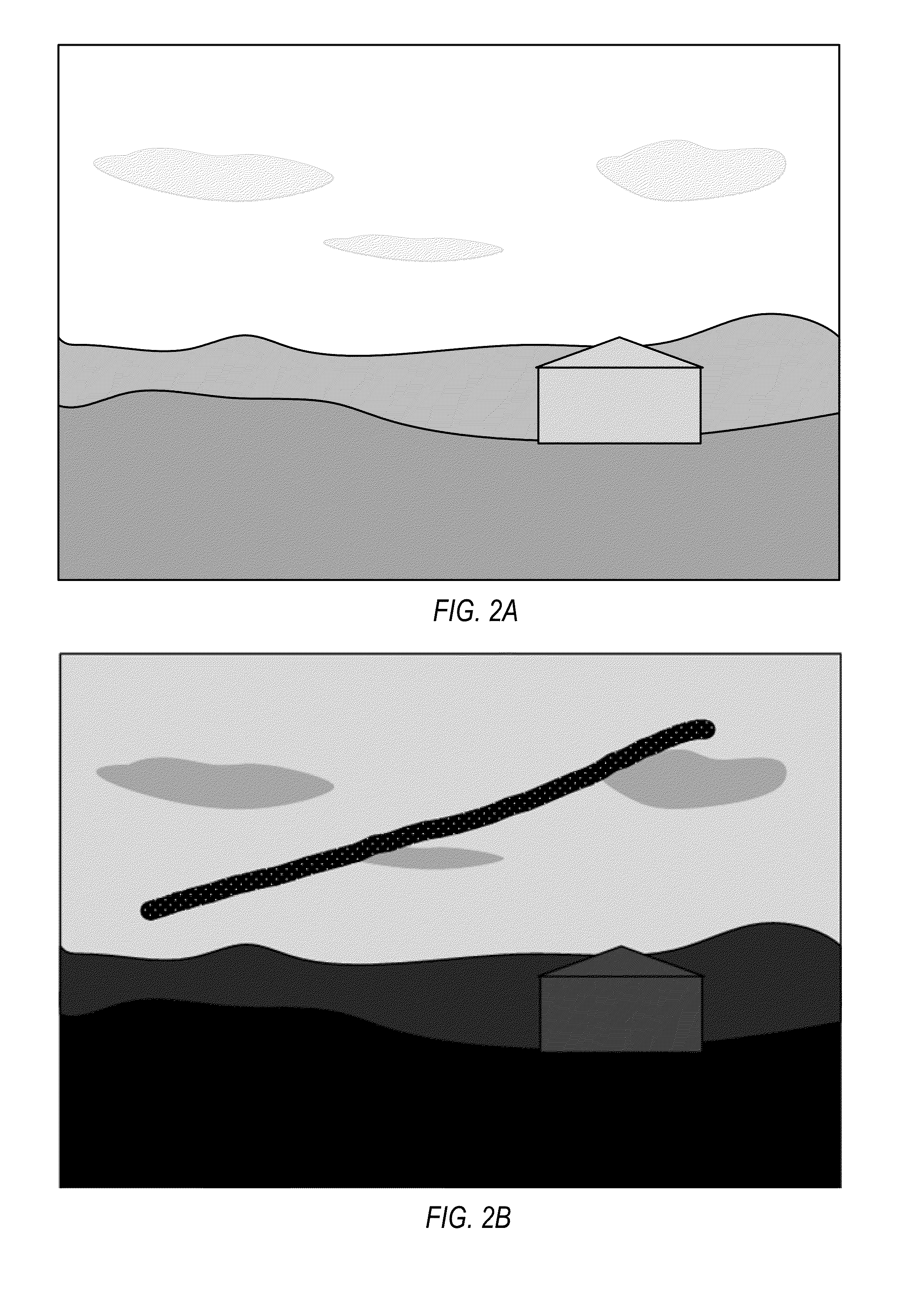
Methods and apparatus for blending regions from multiple images to produce a blended image. An image blending module may obtain multiple digital images of a scene. A base image and a source image are selected, and a stroke is applied to the source image to indicate a desired region which is to be blended with the base image. A region in the source image is identified from the stroke using a segmentation technique such as a graph cut algorithm, and the identified region is blended with the corresponding region of the base image, for example using alpha blending. Additional strokes may be applied to the source image to select other regions to be blended with the base image. A different image may be selected as a source image, and a region from the different image may be selected for blending with the base image.

Description

BACKGROUNDDescription of the Related Art[0001]There are many photographic situations where the range of luminosity values spanning shadows and highlights in a scene is large and thus difficult to capture in a single exposure. For example, objects deep in a room, seen through a small window from outside, can be very dark compared to the outside wall of the house illuminated by direct sunlight. As another example, a single landscape photograph taken near dusk will tend to be either overexposed in the region of the sky to capture detail in the foreground or underexposed in the region of the foreground to capture detail of the sky. In such situations, photographers may capture two or more images of a scene, for example at different exposures (e.g., using different F-stops and / or shutter speeds) or using a flash or other light source to illuminate foreground objects in one image but not in other images. After capturing the two or more images of the scene, various regions from different o...

Claims


Application Information

Patent Timeline
IPC IPC(8): G06K9/34G06K9/36
CPCG06T5/50G06T7/0081G06T11/00G06T2207/20104G06T2207/20221G06T7/0093G06T7/11G06T7/162
Inventor YADAV, VIKAS
Owner ADOBE INC
Learn More