
Preventing pixel modification of an image based on a metric indicating distortion in a 2d representation of a 3D object

Active Publication Date: 2013-05-16
ADOBE INC
View PDF2 Cites 23 Cited by
  • Summary
  • Abstract
  • Description
  • Claims
  • Application Information

AI Technical Summary

Benefits of technology

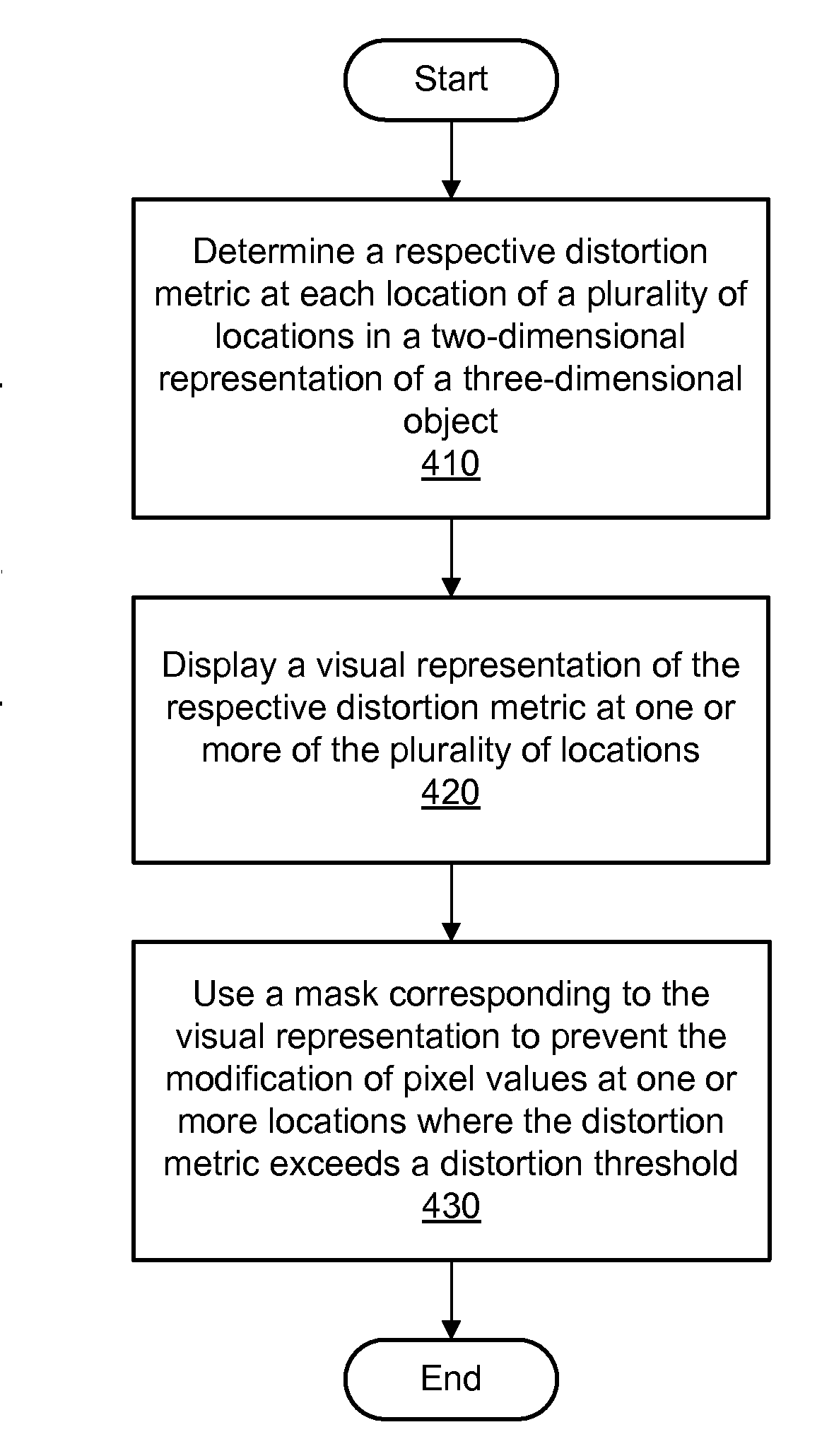
The patent text describes a method for creating a mask to prevent distortion on a three-dimensional object. The mask is generated based on the distortion metrics at different locations on the object. The technique allows for dynamic updating of the mask as the user modifies the view of the object or the resolution of the texture. The technical effect is to improve the accuracy and precision of modifications on the object by preventing distortion in areas where it is not desirable.

Problems solved by technology

These digital image editors may include programs of differing complexity such as limited-purpose programs associated with acquisition devices (e.g., digital cameras and scanners with bundled or built-in programs for managing brightness and contrast); limited editors suitable for relatively simple operations such as rotating and cropping images; and professional-grade programs with large and complex feature sets.

Method used


Image

  • Preventing pixel modification of an image based on a metric indicating distortion in a 2d representation of a 3D object
  • Preventing pixel modification of an image based on a metric indicating distortion in a 2d representation of a 3D object
  • Preventing pixel modification of an image based on a metric indicating distortion in a 2d representation of a 3D object

Examples


Embodiment Construction

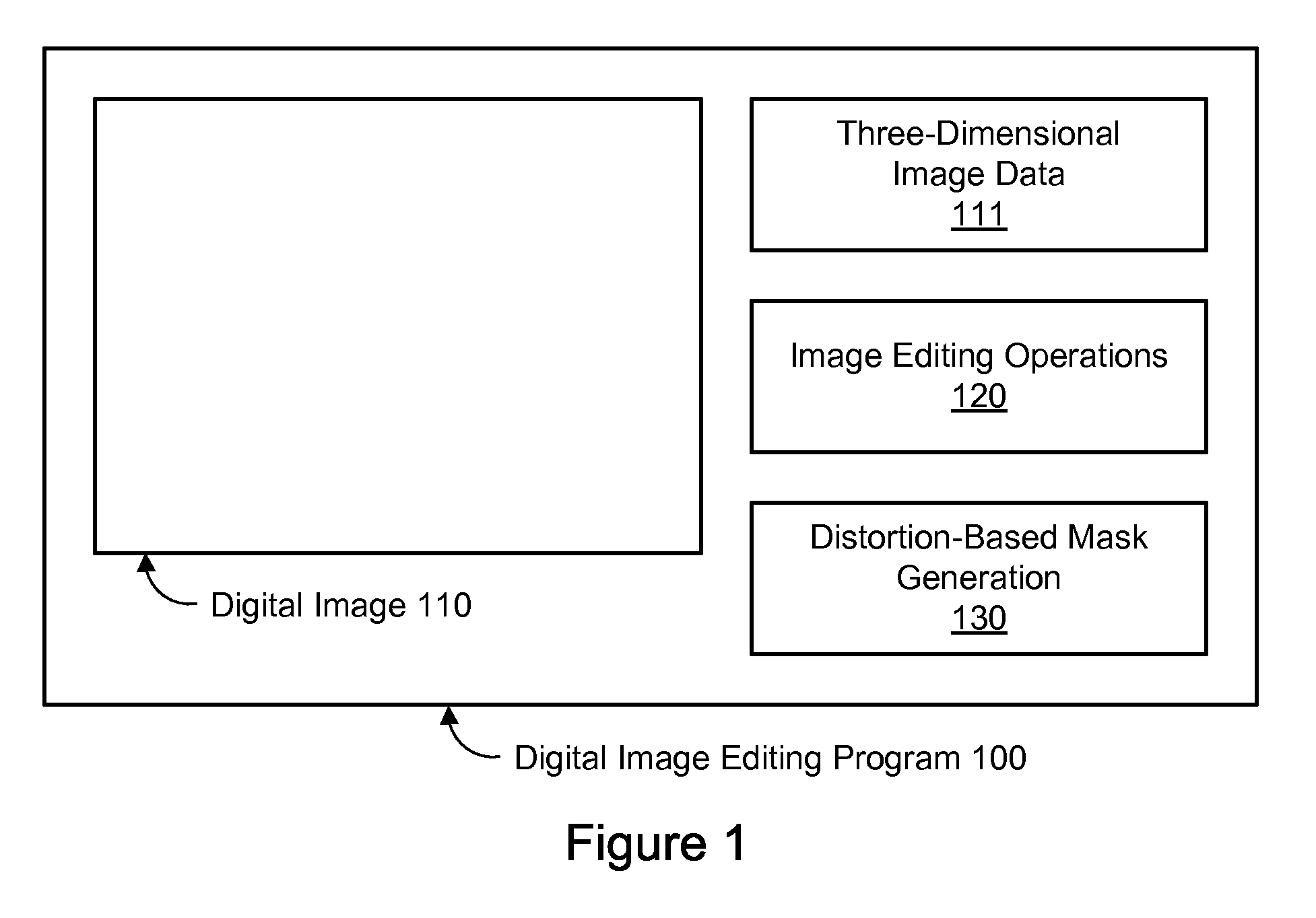
[0016]FIG. 1 is a block diagram illustrating an embodiment of a digital image editing program 100 configured for distortion-based mask generation. A digital image editing program 100, also referred to herein as an image editor 100, may be used to create and / or modify a digital image 110, also referred to herein as an image 110. The digital image editing program 100 may comprise a plurality of editing operations 120. The editing operations 120 may comprise suitable operations for modifying elements of the image 110. For example, various effects such as filters (e.g., Gaussian blur, median filter, add noise, reduce noise, fragment, unsharp mask), image adjustments (e.g., levels, curves, brightness / contrast, shadow / highlight), and other operations (e.g., resizing, cropping, thresholding, rotation, perspective distortion) may be applied to one or more images, selections within the image 110, or other suitable data related to the image 110. In one embodiment, a suitable product such as A...


PUM


Abstract

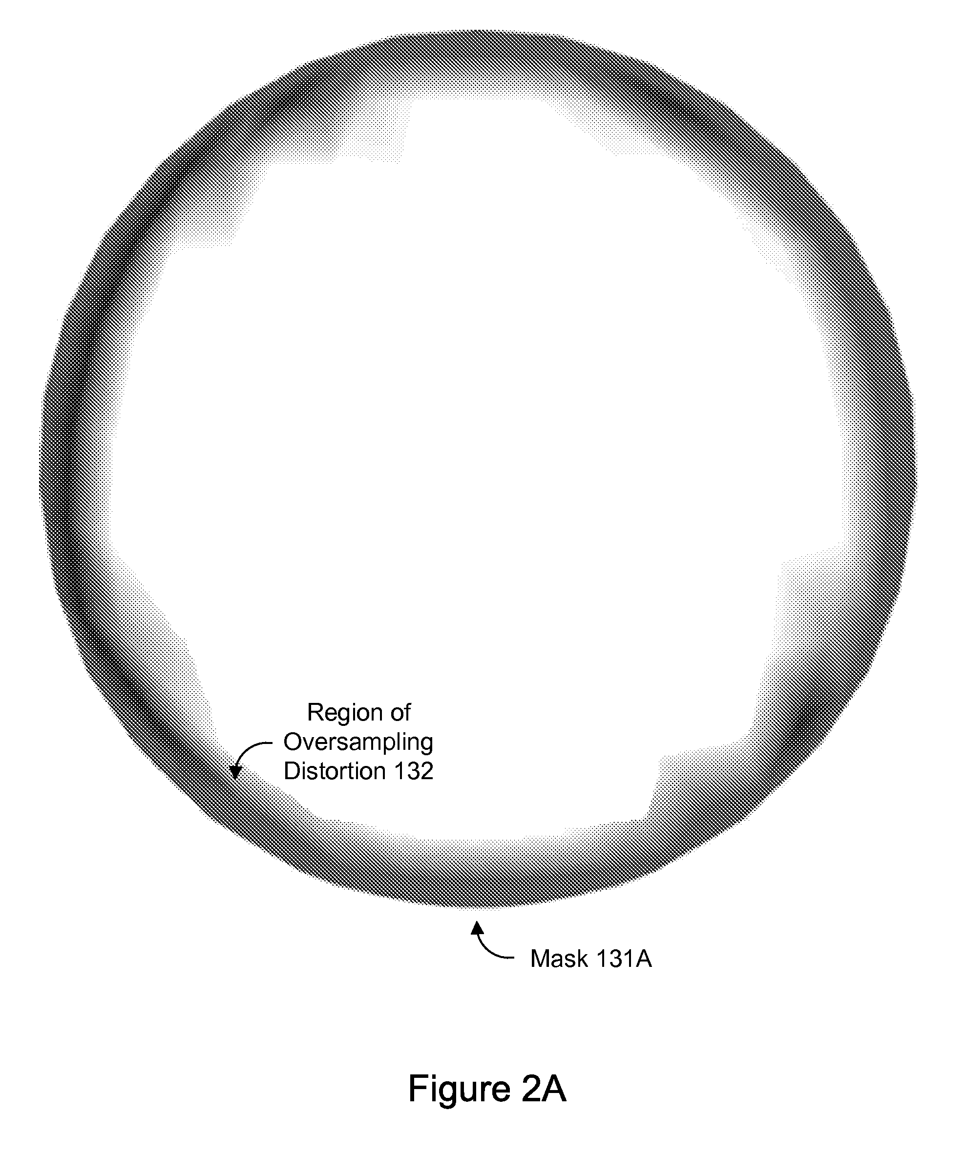
A method, system, and computer-readable storage medium are disclosed for distortion-based mask generation. A respective distortion metric may be determined at each location of a plurality of locations in a two-dimensional representation of a three-dimensional object. The two-dimensional representation may be based on a view of the three-dimensional object. Each respective distortion metric may indicate a degree of distortion in a mapping between the respective location in the two-dimensional representation and a corresponding location in a surface texture of the three-dimensional object. The visual representation of the respective distortion metric at one or more of the plurality of locations may be displayed.

Description

BACKGROUND[0001]1. Field of the Invention[0002]The present invention is directed to computer systems; and more particularly, it is directed to the editing of digital images using computer systems.[0003]2. Description of the Related Art[0004]Digital image editing is the process of creating and / or modifying digital images using a computer system. Using specialized software programs, users may manipulate and transform images in a variety of ways. These digital image editors may include programs of differing complexity such as limited-purpose programs associated with acquisition devices (e.g., digital cameras and scanners with bundled or built-in programs for managing brightness and contrast); limited editors suitable for relatively simple operations such as rotating and cropping images; and professional-grade programs with large and complex feature sets.[0005]Digital images may include raster graphics, vector graphics, or a combination thereof. Raster graphics data (also referred to he...

Claims


Application Information

Patent Timeline
IPC IPC(8): G06K9/03
CPCG06T11/00
Inventor FALCO, JR., PETER F.MILLER, GAVIN S.PCLIFTON, MICHAEL O.CARR, NATHAN A.SVAKHIN, NIKOLAIKRISHNASWAMY, ARAVIND
Owner ADOBE INC
Learn More