
Systems and methods for locking a portable illumination system

a technology of portable illumination and locking mechanism, which is applied in the direction of lighting, instruments, lighting and heating apparatus, etc., can solve the problems of cumbersome switching mechanism, inability to seal for water or weatherproofing purposes, and undesirable portable illumination system with cumbersome switching mechanism, etc., to facilitate the locking of portable illumination system, facilitate the activation of the system, and avoid the effect of inadvertent activation

Active Publication Date: 2013-09-10
BLACK DIAMOND EQUIPMENT
View PDF14 Cites 23 Cited by
  • Summary
  • Abstract
  • Description
  • Claims
  • Application Information

AI Technical Summary

Benefits of technology

The present invention offers a significant improvement in portable illumination systems by reducing the likelihood of accidental activation. The new systems have a locked state that only responds to limited physical user inputs, avoiding inadvertent activation. Additionally, the systems can be waterproof or weatherproof by sealing the switching mechanism. This ensures the safety and reliability of the portable illumination systems. Overall, the invention provides greater security and convenience for users who need to lock their portable lights while keeping them ready for use.

Problems solved by technology

Likewise, conventional portable illumination systems with cumbersome switching mechanisms are undesirable.
While mechanical lockout systems prevent some inadvertent activation, they cannot be sealed for purposes of water or weatherproofing.

Method used


Image

  • Systems and methods for locking a portable illumination system
  • Systems and methods for locking a portable illumination system
  • Systems and methods for locking a portable illumination system

Examples


Embodiment Construction

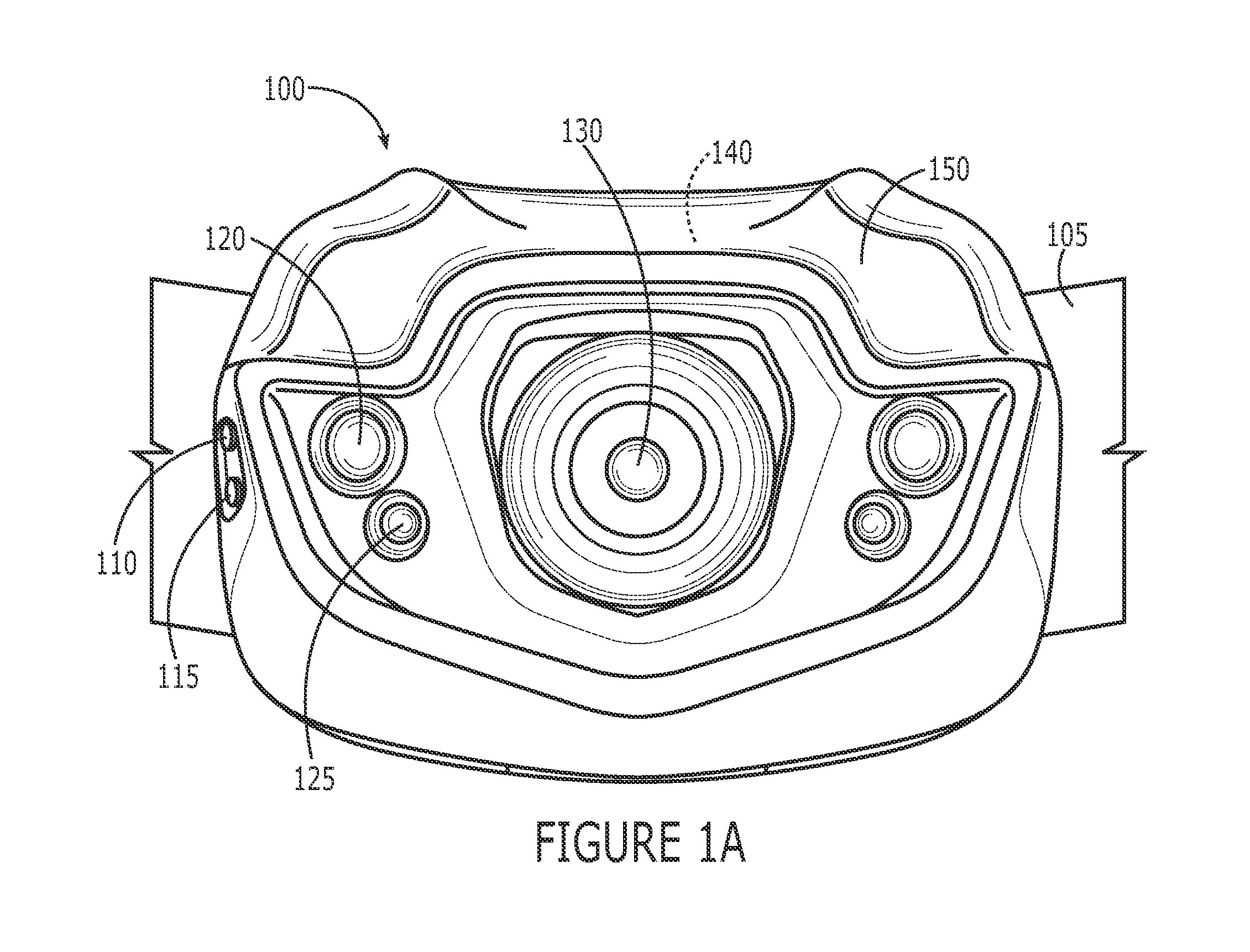
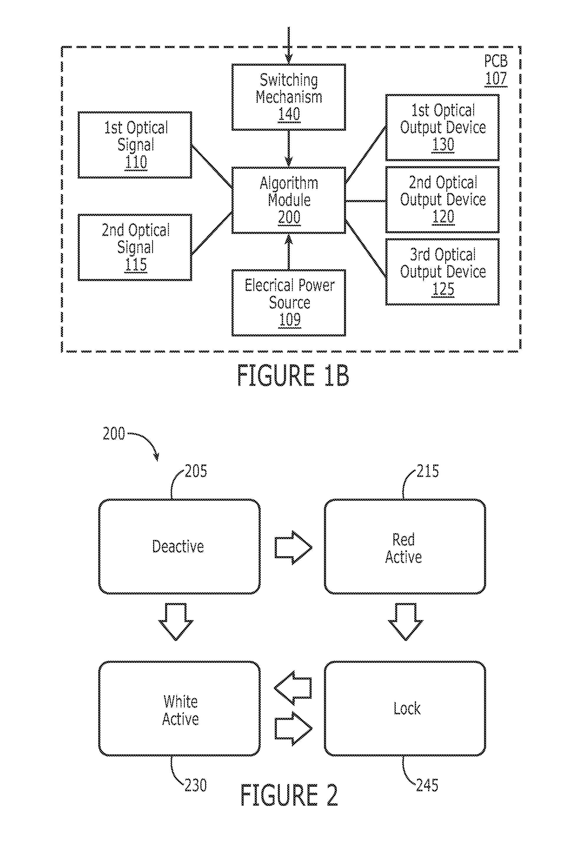
[0015]The present invention relates to portable illumination systems. One embodiment of the present invention relates to a portable illumination system having a locked state that minimizes the occurrence of unintended activation. The system includes an optical output device and an electrical power source such as one or more LEDs and one or more direct current batteries, respectively. The system further includes a first activated state, deactivated state, and locked state. The first activated state comprises an electrical coupling between the electrical power source and the optical output device so as to generate a first optical output via the optical output device. The deactivated state comprises an electrical decoupling between the electrical power source and the optical output device so as to deactivate the optical output device. The locked state also comprises an electrical decoupling between the electrical power source and the optical output device so as to deactivate the optica...


PUM


Abstract

One embodiment of the present invention relates to a portable illumination system having a locked state that minimizes unintended activation. The system includes a first activated state, deactivated state, and locked state. The first activated state generates a first optical output via the optical output device. The deactivated state deactivates the optical output device. The locked state also deactivates the optical output device. The system further includes a switching mechanism configured to receive a first and second physical user input and an algorithm of operation for each of the states. The algorithms of operation for the first activated state and the deactivated state correlate the first and second physical user inputs with a state change between the first activated state, deactivated state, and locked state. The algorithm of operation for the locked state is restricted in that it correlates only the second physical user input with a state change.

Description

RELATED APPLICATIONS[0001]This application claims priority to U.S. provisional application Ser. No. 61 / 307,127 filed Feb. 23, 2010, the contents of which are incorporated by reference.FIELD OF THE INVENTION[0002]The invention generally relates to portable illumination systems. In particular, the present invention relates to system and methods for operationally locking a portable illumination system.BACKGROUND OF THE INVENTION[0003]Illumination systems selectively transmit a region or field of illumination that may be used for a variety of purposes. The illuminated region may be used to provide various forms of light to assist a user in performing visual tasks and / or designating a location for others. For example, a headlamp is an illumination system which is commonly coupled to a user's head and is used to illuminate a region in alignment with the orientation of the user's head. Likewise, a flashlight is a handheld illumination system which illuminates a region in alignment with the...

Claims


Application Information

Patent Timeline
Patent Type & Authority Patents(United States)
IPC IPC(8): H01H83/00F21L4/00F21K2/00F21L4/02F21V33/00H01H35/00
CPCG03B21/14G03B15/02F21V23/0414F21Y2101/02Y10T307/766F21Y2115/10
Inventor SKRIVAN, JOSEPHHEINRICH, DOUGLASSAXTON, JEREMY ALLENBEST, CHRISTOPHER
Owner BLACK DIAMOND EQUIPMENT
Learn More