Non-energetics based detonator

a non-energetic, detonator technology, applied in the field of detonators, can solve the problems of shock wave, voltage and power requirements to function this type of conventional hot wire igniter, and the heat of the fuse head

Active Publication Date: 2013-05-23
BATTELLE MEMORIAL INST
View PDF16 Cites 29 Cited by
  • Summary
  • Abstract
  • Description
  • Claims
  • Application Information

AI Technical Summary

Benefits of technology

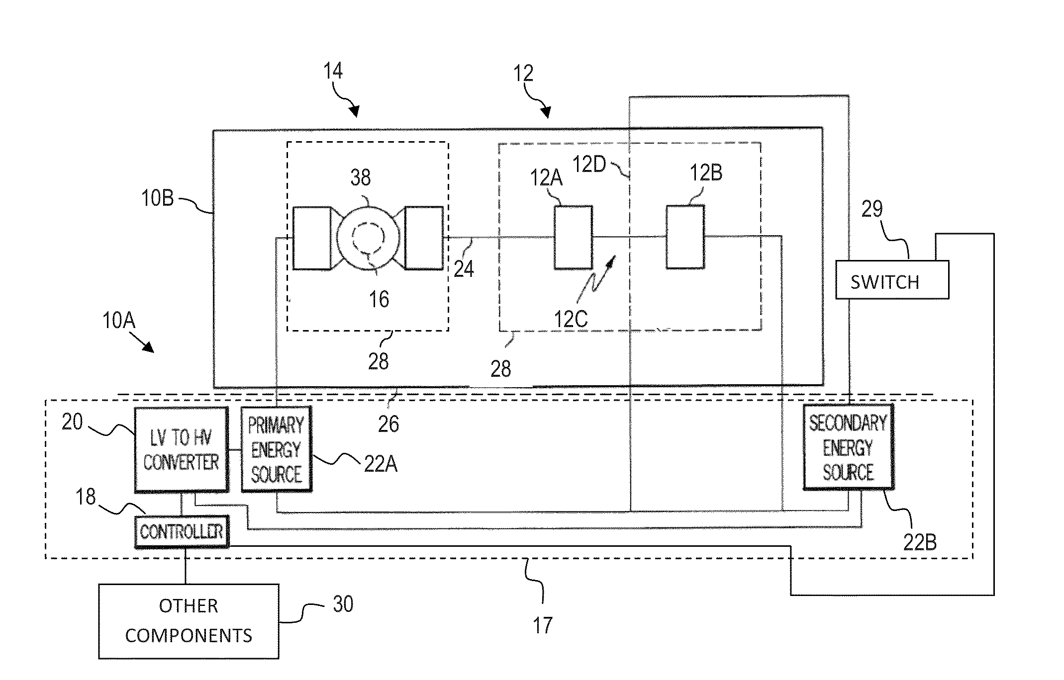
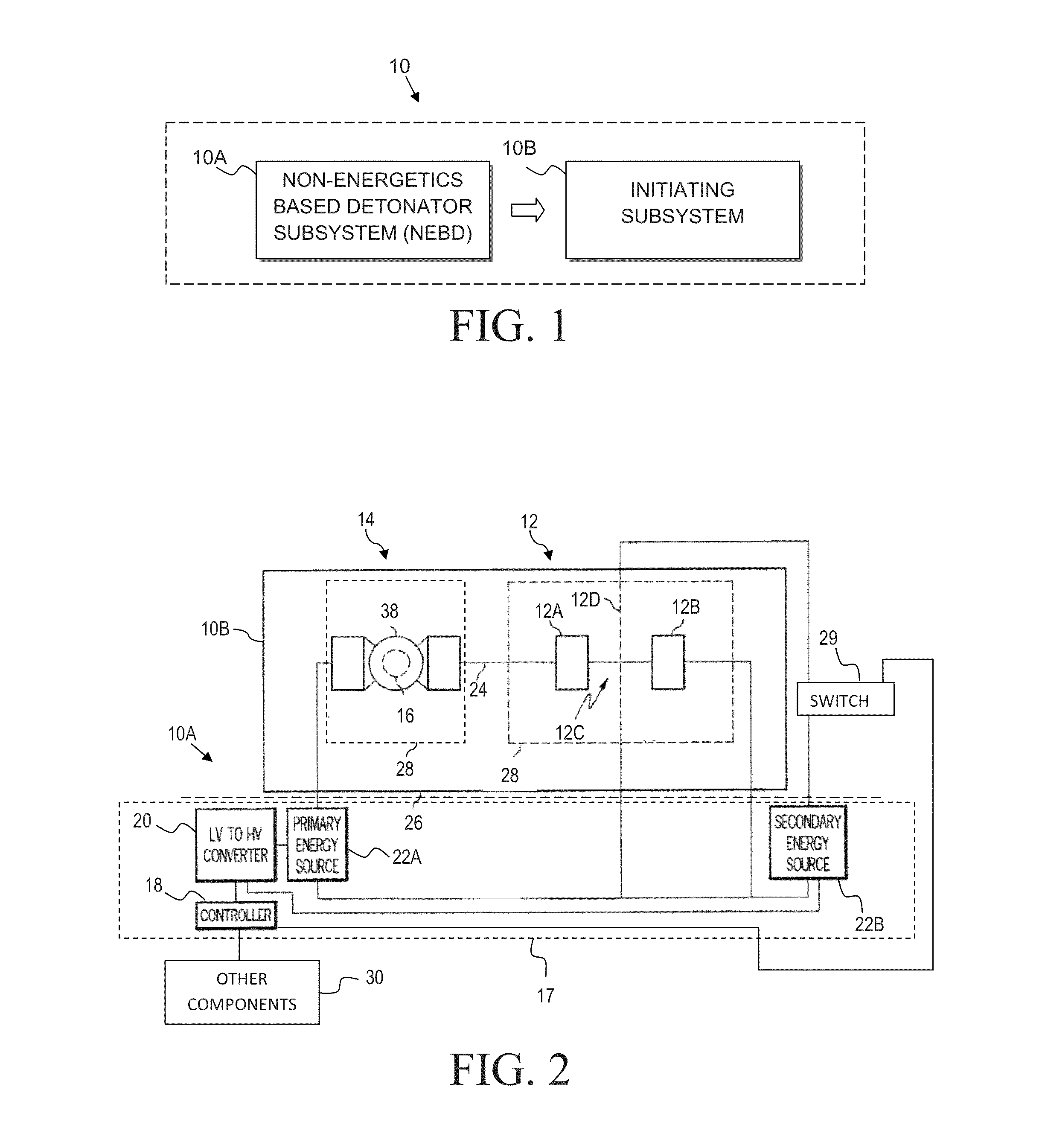
[0007]According to aspects of the present invention, the non-energetics based subsystem comprises a controller, a low voltage to high voltage converter controlled by the controller, a primary energy source coupled to the low voltage to high voltage converter, a secondary energy source controlled by the controller and a first interface. The first interface includes a first pair of conductive contacts spaced by an insulator, where each of the conductive contacts of the first pair is electrically coupled to a circuit path associated with the primary energy source.
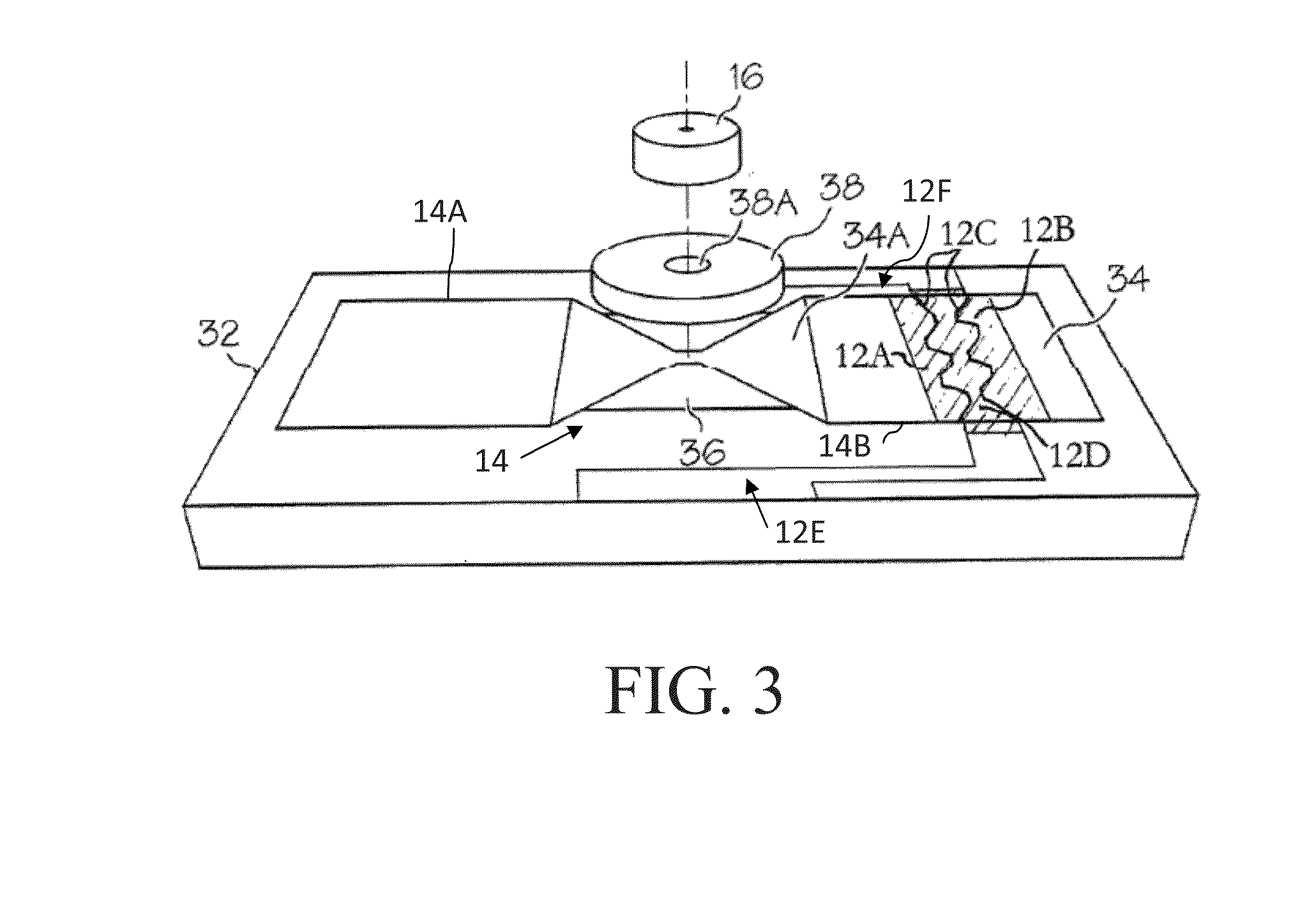
[0008]The initiating subsystem comprises a high voltage switch, an initiator electrically coupled in series with the high voltage switch, an initiating pellet positioned in cooperation with the initiator, and a second interface. The initiating pellet has explosive material comprising at least one insensitive secondary explosive material. However, the explosive material is free of sensitive primary explosive material. Moreover, the initiating pellet is positioned such that functioning the initiator detonates the explosive material of the initiating pellet. The second interface mates with the first interface to electrically connect a first conductive path from the primary energy source to the circuit of the high voltage switch and initiator. The second interface including a first pair of interface legs positioned so that each interface leg of the first pair mates with a corresponding one of the first pair of conductive contacts of the first interface when the initiating subsystem is suitably mated with the non-energetics based subsystem.
[0009]The interface legs of the second interface are self-shunting and thus short to one another when the initiating subsystem is removed from the non-energetics based subsystem. Further, the insulator of the first interface is arranged so as to separate the self-shunting legs and guide each leg to a corresponding one of the conductive contacts when the non-energetics based subsystem is suitably assembled with the initiating subsystem by mating the first interface with the second interface.
[0010]Moreover, in a further embodiment, the first interface of the non-energetics based subsystem further comprises a second pair of conductive contacts spaced by the insulator, where each of the conductive contacts of the second pair is electrically coupled to a circuit path associated with the secondary energy source. Correspondingly, the second interface of the initiating subsystem comprises a second pair of interface legs positioned so that each interface leg of the second pair mates with a corresponding one of the second pair of conductive contacts of the first interface when the initiating subsystem is suitably mated with the non-energetics based subsystem and the se

Problems solved by technology

Such hot wire igniters operate by delivering a low voltage electrical pulse to the fuse head, causing the fuse head to heat up.
However, conventional hot wire igniters must rely on an extremely sensitive primary explosive to transition the detonation process from the fuse head to the corresponding explosive output pellet.
Moreover, it is possible that the voltage and power

Method used


Image

  • Non-energetics based detonator
  • Non-energetics based detonator
  • Non-energetics based detonator

Examples


Embodiment Construction

[0046]According to various aspects of the present invention, a two-component detonator device for use with explosives comprises two subsystems. A first subsystem functions as a fireset and does not contain any explosives. The second subsystem includes an initiating pellet that is capable of directly firing an insensitive secondary explosive material. Moreover, the two subsystem detonator device may be implemented in “basic” detonator configurations or in “enhanced” detonator configurations, according to various aspects of the present invention, as described more fully herein. The discussion herein with reference to FIGS. 1 through 3 is applicable to both basic and enhanced detonator implementations.

Two-Component Detonator Overview

[0047]Referring now to the drawings and in particular to FIG. 1, a detonator device 10 according to various aspects of the present invention includes two subsystems, including a non-energetics based subsystem 10A (also referred to herein as a non-energetics...


PUM


Abstract

A detonator system is provided for use with explosives that utilizes two subsystems. A first subsystem functions as a non-explosives based detonator, which does not contain any explosives. The second subsystem is an initiating subsystem, which includes an initiating pellet. To set off an explosive event, the non-energetics based detonator is coupled to the initiating subsystem and the non-energetics based detonator is commanded to provide a suitable signal to the initiating subsystem that is sufficient to function the initiating pellet. Further, the initiating subsystem can be integrated directly into an associated explosive such as a booster that has been configured to receive the initiator subsystem without changing the hazard class of the booster.

Description

CROSS REFERENCE TO RELATED APPLICATIONS[0001]This application is a continuation of International Application No. PCT / US2011 / 041003, filed Jun. 17, 2011, entitled “NON-ENERGETICS BASED DETONATOR”, which claims the benefit of U.S. Provisional Patent Application Ser. No. 61 / 356,424, filed Jun. 18, 2010, entitled “NON-ENERGETICS BASED DETONATOR”, the disclosures of which are hereby incorporated by reference.BACKGROUND[0002]The present invention relates to detonators, and more particularly, to non-energetics-based detonators, detonator systems using non-energetics based detonators and methods of detonating explosives.[0003]In various industries, such as mining, construction and other earth moving operations, it is common practice to utilize detonators to initiate explosives loaded into drilled blast holes for the purpose of breaking rock. For instance, commercial electric and electronic detonators are conventionally implemented as hot wire igniters that include a fuse head as the initiat...

Claims


Application Information

Patent Timeline
IPC IPC(8): F42D1/05
CPCF42B3/121F42D1/05F42B3/182F42B3/122F42B3/10F42D1/055F42D5/00
Inventor BACKHUS, ROGER F.GIVENS, RICHARD W.KLEIN, JEROME A.LOESER, RONALD L.PAUGH, JASON E.VANCLEAVE III, WALTER G.ZIMMER, ISAAC THOMAS
Owner BATTELLE MEMORIAL INST
Why Eureka
Try Eureka