

Pass-through Bulkhead Connection Switch for a Perforating Gun
- Summary
- Abstract
- Description
- Claims
- Application Information
AI Technical Summary
Benefits of technology
Problems solved by technology
Method used
Image

Examples
Embodiment Construction
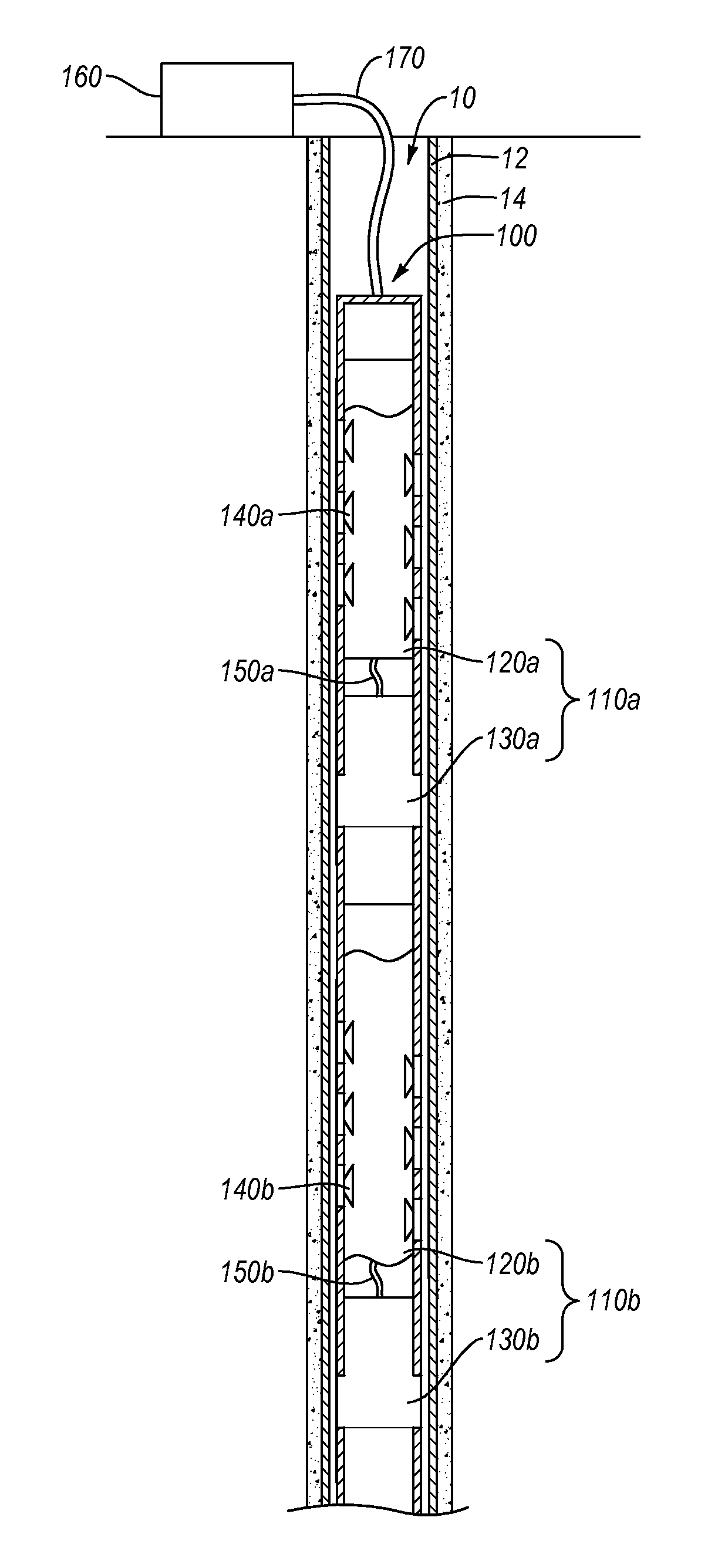
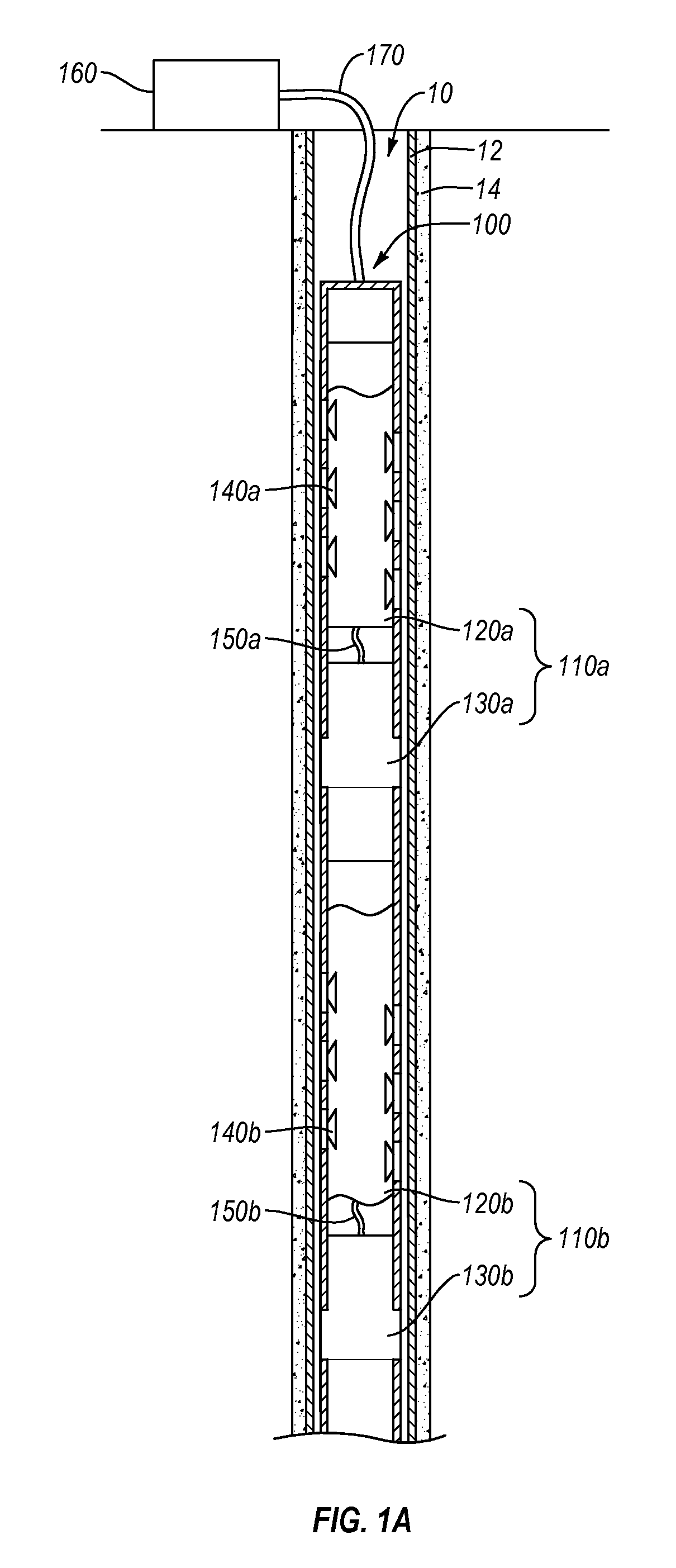
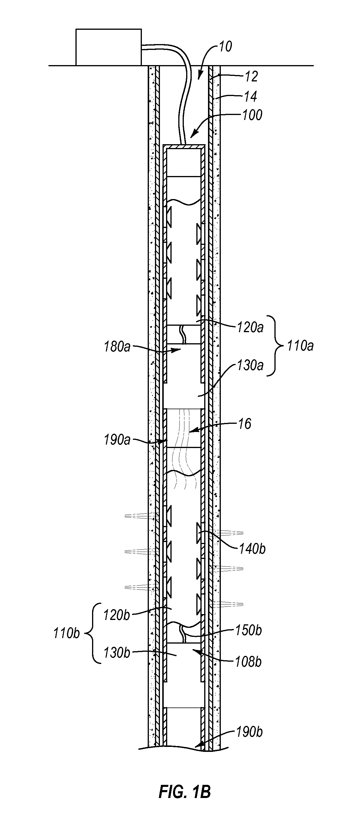
[0026]Embodiments of the present invention provide systems, methods, and apparatus for reliably communicating a detonation signal or command and perforating oil and / or gas well casings. Particularly, at least one embodiment includes a pass-through bulkhead connection switch that can reliably withstand high operating temperatures and pressures. Such pass-through bulkhead connection switch can be used in perforating gun assemblies and can eliminate or reduce incidents of failed detonations. Accordingly, the pass-through bulkhead connection switch can lead to reduced accidents during oil and gas drilling and / or exploration costs. Furthermore, reduction or elimination of failed detonations also can reduce or eliminate the need for withdrawing the perforating gun assemblies from the well before completing well perforations. Consequently, the reliable pass-through bulkhead connection switch can reduce instances of surface detonation, which also can improve worker safety.
[0027]The pass-thr...
PUM
 Abstract
Description
Claims
Application Information