Supercharge Your Innovation With Domain-Expert AI Agents!

Hydro-pneumatic suspension system

a technology of hydraulic springs and suspension systems, applied in the direction of resilient suspensions, vehicle springs, vibration dampers, etc., can solve the problem of negative effect of vehicle roll when cornering

Inactive Publication Date: 2013-05-23
TIMONEY SEAN +1
View PDF5 Cites 0 Cited by
  • Summary
  • Abstract
  • Description
  • Claims
  • Application Information

AI Technical Summary

Benefits of technology

The patent describes a suspension system for vehicles that uses a hydro-pneumatic spring to absorb shocks and reduce the force exerted on the vehicle body. The system also includes a compensating spring that acts to reduce the suspension force as the hydro-pneumatic spring reaches its maximum extension. The compensating spring helps to balance the force between the vehicle body and the control arms, improving the stability of the vehicle.

Problems solved by technology

The non-linear spring characteristic, while advantageous as the spring is compressed towards the full bump position, creates a problem as the spring is extended towards the full rebound position because at full rebound, there is usually a large residual force remaining in the spring.
This has an adverse effect on vehicle roll when cornering.

Method used


Image

  • Hydro-pneumatic suspension system
  • Hydro-pneumatic suspension system
  • Hydro-pneumatic suspension system

Examples


Embodiment Construction

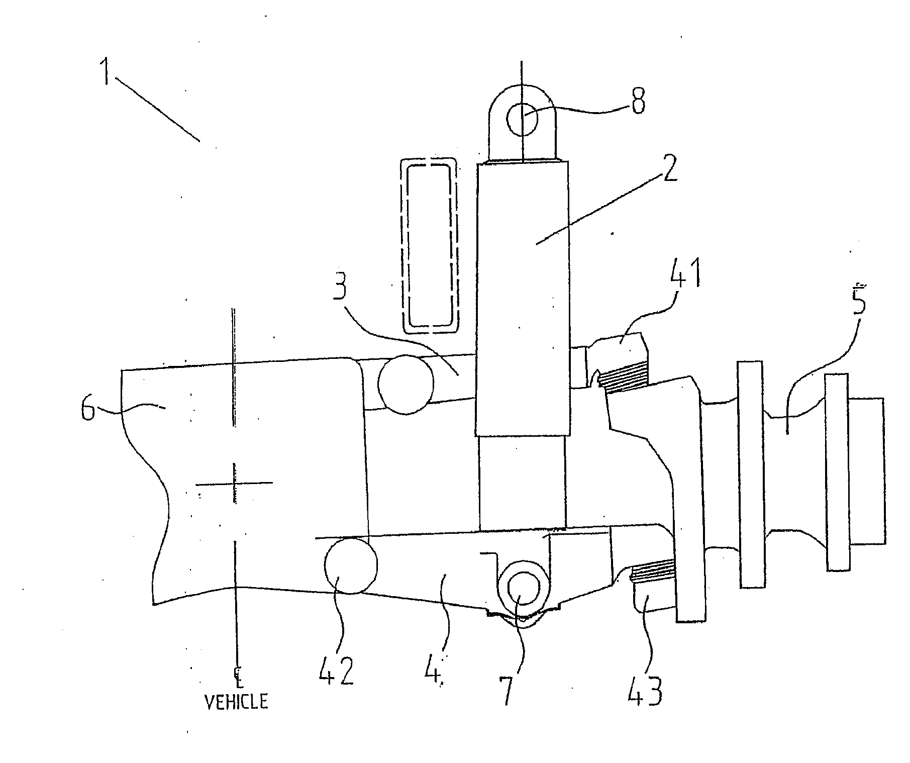
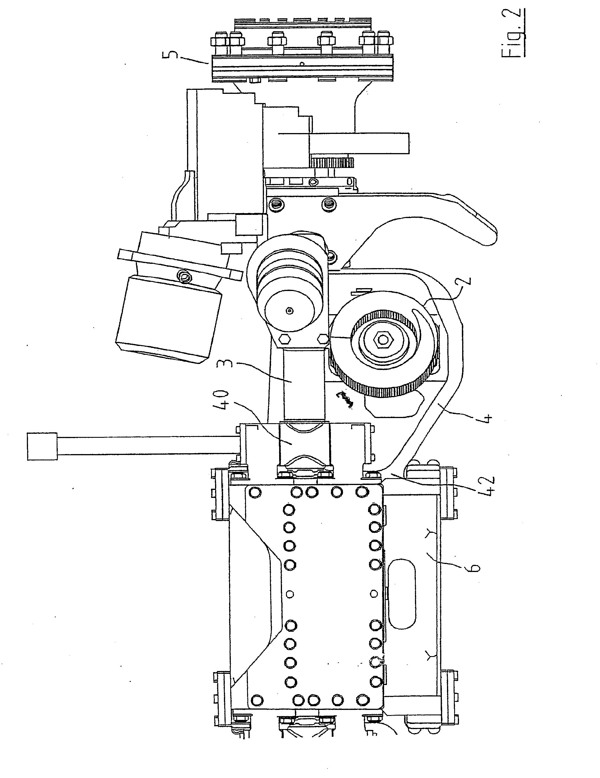
[0030]Referring to the drawings, and initially to FIG. 1 thereof, there is illustrated one side of an independent wheel suspension system according to the invention, indicated generally by the reference numeral 1, the other side of the system, which is located at an opposite side of the vehicle, being similar. The suspension system 1 incorporates a hydrostrut, hydraulic suspension actuator or hydro-pneumatic spring 2. In this case, the suspension system incorporates an upper control arm 3 and a lower control arm 4 to locate a wheel carrier 5 with respect to a vehicle body 6. The hydro-pneumatic spring 2 is connected at its upper end to the vehicle body 6 by an articulated joint 8 and at its lower end 7 to the lower control arm 4. It will be understood that this type of suspension system is shown for the purpose of illustration only and that the invention may be used in conjunction with many different types of suspension system. The hydro-pneumatic spring 2 is under compression and p...


PUM


Abstract

A suspension system for a vehicle has an upper control arm and an associated lower control arm for mounting a wheel on the vehicle body. A hydro-pneumatic spring is connected between one of the control arms and the vehicle body. A compensating spring is associated with the hydro-pneumatic spring and is operable to act in opposition to the force exerted by the hydro-pneumatic spring as the hydro-pneumatic spring approaches full extension.

Description

BACKGROUND OF THE INVENTION[0001]This application is a Continuation of co-pending application Ser. No. 11 / 653,831 filed on Jan. 17, 2007, which is a Continuation of co-pending application Ser. No. 10 / 883,774 filed on Jul. 6, 2004 and for which priority is claimed under 35 U.S.C. §120; and this application claims priority of Application No. S2001 / 0125 filed in Ireland on Feb. 9, 2001 under 35 U.S.C. §119; the entire contents of all are hereby incorporated by reference.FIELD OF THE INVENTION[0002]This invention relates to hydro-pneumatic springs and in particular to hydro-pneumatic springs used in vehicle suspension systems.DESCRIPTION OF RELATED ART[0003]A hydro-pneumatic spring uses hydraulic fluid to transmit force to a variable volume gas chamber which acts as a spring. Hydro-pneumatic suspension systems for vehicles offer a number of advantages which include a rise in spring rate as the spring is compressed into bump and the possibility of adding additional features such as integ...

Claims


Application Information

Patent Timeline
Patent Type & Authority Applications(United States)
IPC IPC(8): B60G11/56F16F13/00B60G17/04B60G17/048F16F9/06F16F9/48
CPCB60G11/58F16F13/002B60G15/12B60G17/04B60G17/048B60G2200/144B60G2200/44B60G2202/12B60G2202/154B60G2204/129B60G2204/19B60G2204/416B60G2204/45B60G2204/4504B60G2206/422B60G2500/20F16F9/06F16F9/065F16F9/48B60G11/56B60G15/061
Inventor TIMONEY, SEANANDERSON, COLIN JAMES
Owner TIMONEY SEAN
Features
  • R&D
  • Intellectual Property
  • Life Sciences
  • Materials
  • Tech Scout
  • Unparalleled Data Quality
  • Higher Quality Content
  • 60% Fewer Hallucinations
Learn More