
Method and apparatus for reliably laser marking articles

a laser marking and laser technology, applied in the direction of duplicating/marking methods, printing, etc., can solve the problems of material, time and resources, damage to the anodization, measuring the duration of complex pulses, etc., and achieve the effect of commercially desirable appearan

Inactive Publication Date: 2013-05-23
ELECTRO SCI IND INC
View PDF6 Cites 3 Cited by
  • Summary
  • Abstract
  • Description
  • Claims
  • Application Information

AI Technical Summary

Benefits of technology

The solution enables the creation of durable, commercially desirable marks on anodized aluminum without damaging the oxide layer, ensuring consistent appearance and ease of application, and allows for the production of marks with precise control over color and optical density, including grayscale and color variations.

Problems solved by technology

Ease of application refers to the cost in materials, time and resources of producing a mark including programmability.
An issue is that measuring the duration of complex pulses such as these using standard methods typically applied to Gaussian pulses can yield anomalous results.
Another problem with reliably and repeatably producing marks with desired color and optical density in anodized aluminum is that the energy required to create very dark marks with readily available nanosecond pulse width solid state lasers is enough to cause damage to the anodization, an undesirable result.
Making marks according to the methods claimed in this patent are disadvantageous for two reasons: first, creating commercially desirable black marks with nanosecond-range pulses tends to cause destruction of the oxide layer and secondly, cleaning of the aluminum following polishing or other processing adds another step in the process, with associated expense, and possibly disturbs a desired surface finish by further processing.
In addition, no information is supplied on how to repeatably create various colors on anodized aluminum surfaces, nor has the effects of bleaching or damage to the anodization layer been thoroughly investigated.

Method used


Image

  • Method and apparatus for reliably laser marking articles
  • Method and apparatus for reliably laser marking articles
  • Method and apparatus for reliably laser marking articles

Examples


Embodiment Construction

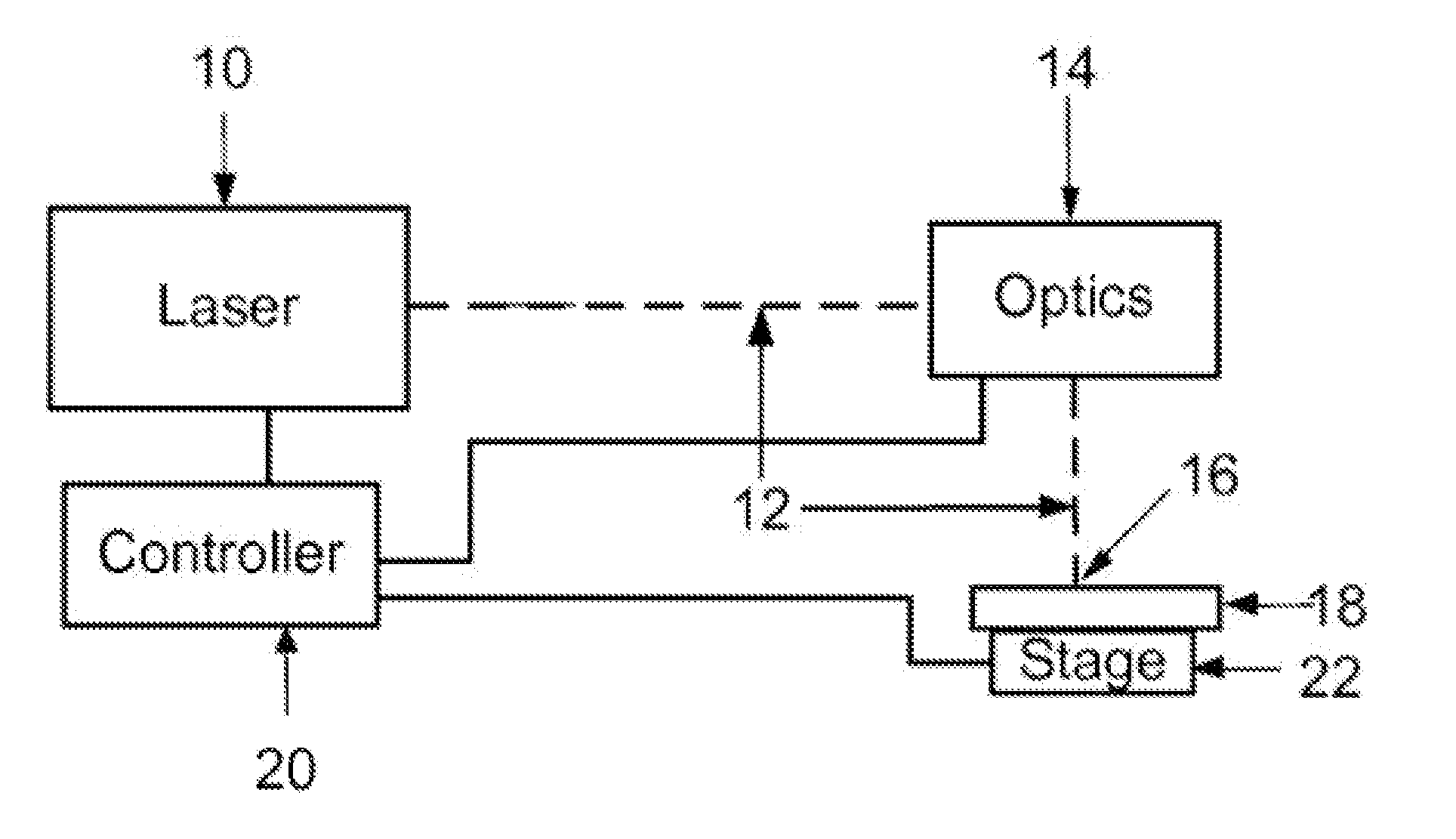
[0027]A goal of this invention is to mark anodized aluminum articles with visible marks of various optical densities and colors, durably, selectably, predictably, and repeatably. It is advantageous for these marks to appear on or near the surface of the aluminum and leave the anodization layer substantially intact to protect both the surface and the marks. Marks made in this fashion are referred to as interlayer marks since they are made at or on the surface of the aluminum beneath the oxide layer that forms the anodization. Ideally the oxide remains intact following marking in order to protect the marks and provide a surface that is mechanically contiguous between adjacent marked and non-marked regions. Further, these marks should be able to be produced reliably and repeatably, meaning that if a mark with a specific color and optical density is desired, a set of laser parameters is known which will produce the desired result when the anodized aluminum is processed by a laser proces...


PUM

PropertyMeasurementUnit
optical densityaaaaaaaaaa
wavelengthaaaaaaaaaa
average poweraaaaaaaaaa

Abstract

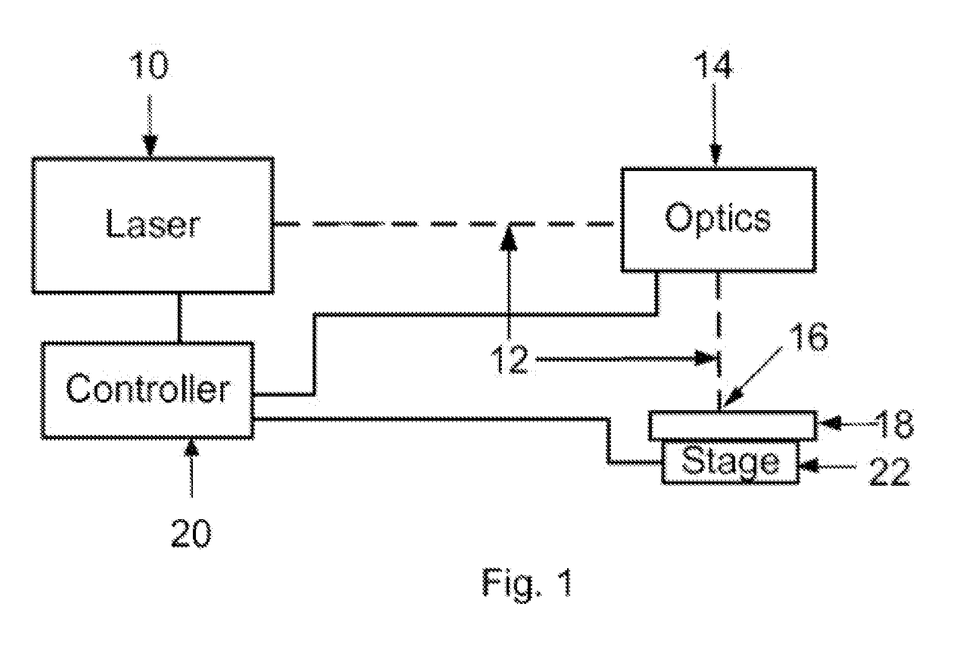
The invention is a method and apparatus for creating a color and optical density selectable visible mark on an anodized aluminum specimen. The method includes providing a laser marking system having a laser, laser optics and a controller operatively connected to said laser to control laser pulse parameters and a controller with stored laser pulse parameters, selecting the stored laser pulse parameters associated with the desired color and optical density, directing the laser marking system to produce laser pulses having laser pulse parameters associated with the desired color and optical density including temporal pulse widths greater than about 1 and less than about 1000 picoseconds to impinge upon said anodized aluminum.

Description

CROSS REFERENCE TO RELATED APPLICATIONS[0001]This application is a continuation of U.S. patent application Ser. No.12 / 704,293, filed on Feb. 11, 2010, which is incorporated herein by reference in its entirety.TECHNICAL FIELD[0002]The present invention relates to laser marking of anodized aluminum articles. In particular it relates to marking anodized aluminum with a laser processing system. More particularly it relates to marking anodized aluminum in a durable and commercially desirable fashion with a laser processing system. Specifically it relates to characterizing the interaction between visible and infrared wavelength picosecond laser pulses and the anodized aluminum to reliably and repeatably create durable marks with a desired color and optical density.BACKGROUND OF THE INVENTION[0003]Marketed products commonly require some type of marking on the product for commercial, regulatory, cosmetic or functional purposes.[0004]Desirable attributes for marking include consistent appear...

Claims


Application Information

Patent Timeline
Patent Type & Authority Applications(United States)
IPC IPC(8): B41J2/44
CPCB41M5/262B41J2/442
Inventor ZHANG, HAIBINSIMENSON, GLENNHAINSEY, ROBERTBARSIC, DAVIDHOWERTON, JEFFREYCROWTHER, WAYNELEONARD, PATRICK
Owner ELECTRO SCI IND INC
Learn More