Multi-relay transmission apparatus and method using interference alignment

Inactive Publication Date: 2013-05-23
SAMSUNG ELECTRO MECHANICS CO LTD +1
View PDF1 Cites 6 Cited by
  • Summary
  • Abstract
  • Description
  • Claims
  • Application Information

AI Technical Summary

Benefits of technology

The present invention provides a way to transfer data between a base station and a terminal using multiple relay nodes. This method helps to minimize the impact on data transfer speed caused by interference between the base station and the relay nodes. Additionally, the invention allows for continuous data transfer between the base station and the terminal through multiple relays in a system with a single source and destination. This results in increased efficiency and reliability of data transfer.

Problems solved by technology

Meanwhile, in an actual relay environment, uni-directional communications (a half-duplex relay scheme), rather than bi-directional communications (a full-duplex relay scheme), have been considered due to problems in system implementation, complexity, and the like.
However, uni-directional communications involve a problem in which frequency efficiency is halved, which leads to a reduction in the pre-log factor (or the degree of freedom) of a total transfer rate.
In this case, however, signals between or among multiple relays may act as interference signals, so a technique of effectively controlling interference signals is required.
Existing uni-directional communications use a scheme of transmitting a signal from a source node to a destination node by using a half-duplex relay, and have a problem in which frequency efficiency is halved due to the use of the half-duplex relay.
Namely, unlike a scheme in which a source node directly transfers a signal to a destination node, the half-duplex relay scheme has degraded frequency efficiency because a signal is transmitted through a relay.
However, in the existing multi-relay system, even with the selective relay scheme, the problem in which the degree of freedom of a total data transfer rate is degraded remains unsolved.

Method used


Image

  • Multi-relay transmission apparatus and method using interference alignment
  • Multi-relay transmission apparatus and method using interference alignment
  • Multi-relay transmission apparatus and method using interference alignment

Examples


first embodiment

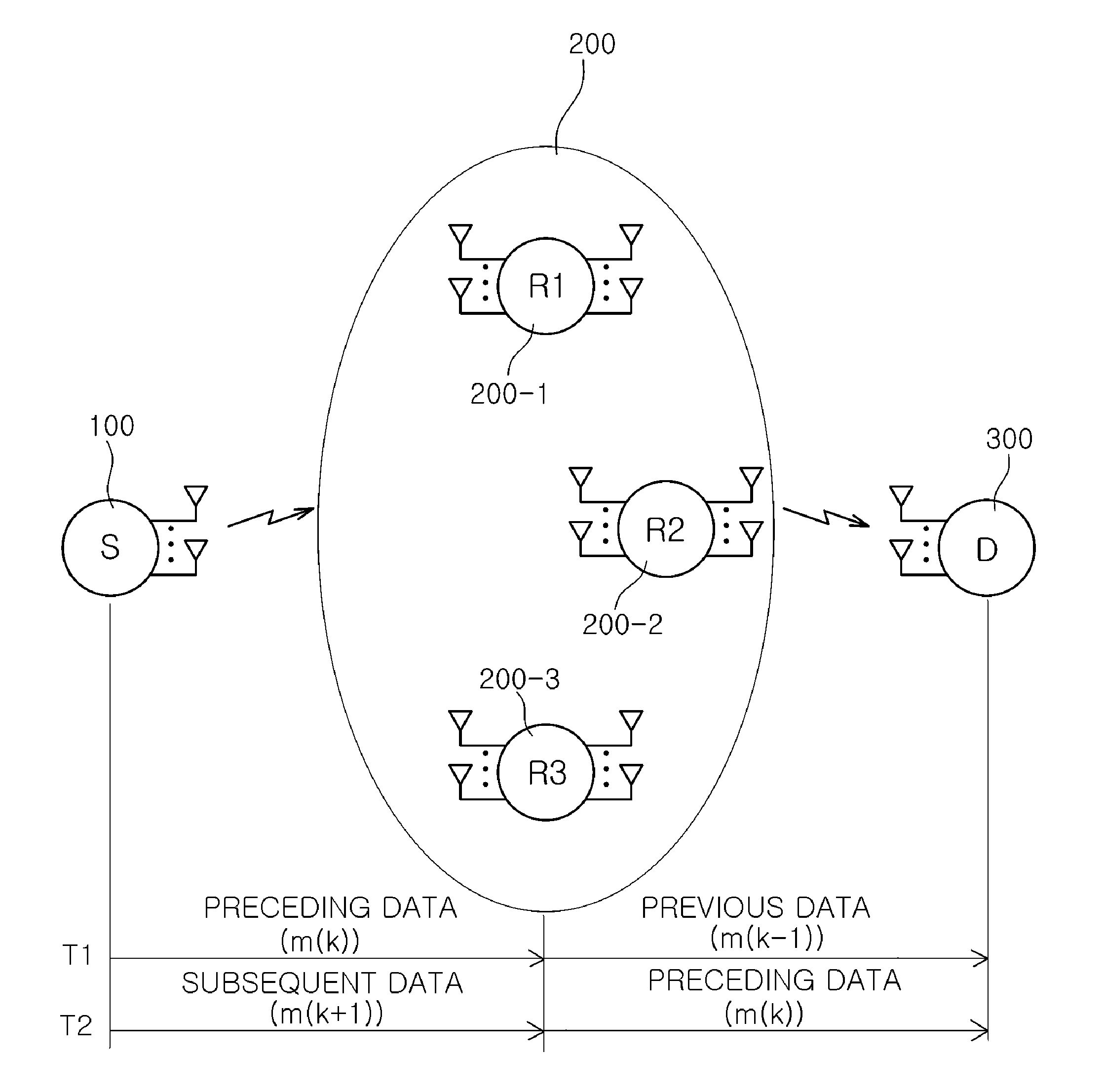
[0047]FIG. 1 is a view showing the configuration of a multi-relay transmission apparatus according to the present invention.

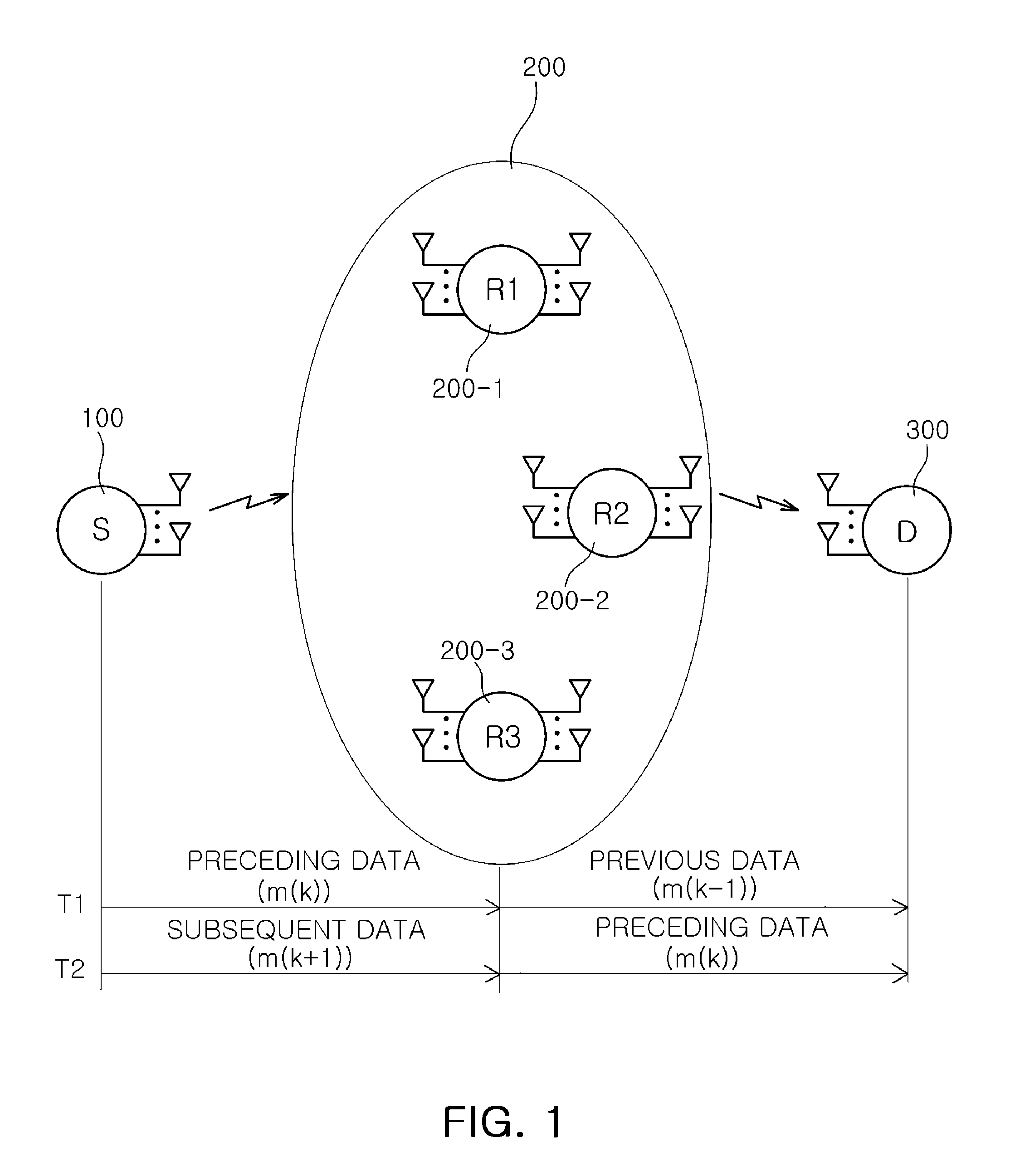
[0048]With reference to FIG. 1, a multi-relay transmission apparatus according to a first embodiment of the present invention may include a source node 100, a relay network 200, and a destination node 300.

[0049]In FIG. 1, the source node 100 may alternately repeat a first phase in which preceding data is transmitted during a first transmission period T1 equivalent to a transmission period during which unit frames can be transmittable at a time in transmitting data frames, and a second phase in which subsequent data that follows the preceding data is transmitted during a second transmission period T2 that follows the first transmission period T1.

[0050]The relay network 200 includes a plurality of relay nodes R1, R2, and R3 receiving data from the source node 100. In the first phase, a predetermined relay node R3, among the plurality of relay nodes R1, R2, and R3...

second embodiment

[0068]FIG. 3 is a flow chart illustrating a process of a multi-relay transmission method according to the present invention.

[0069]With reference to FIG. 3, the multi-relay transmission method according to the second embodiment of the present invention may include a determination step S310, a first phase performing step S320, and a second phase performing step S330.

[0070]First, in the determination step S310, the source node 100 may determine whether it has data to be transmitted.

[0071]In the first phase performing step S320, when the source node 100 has data to be transmitted, it may perform a first phase to transmit preceding data during a first transmission period T1, equivalent to a transmission period during which unit frames can be transmittable at a time in transmitting data frames.

[0072]Here, in the first phase, the predetermined one predetermined relay node R3 among the plurality of relay nodes R1, R2, and R3 may receive the preceding data from the source node 100, and the r...

third embodiment

[0084]FIG. 4 is a flow chart illustrating a process of a multi-relay transmission method according to the present invention.

[0085]With reference to FIG. 4, the multi-relay transmission method according to a third embodiment of the present invention may include a determination step S410, a second phase performing step S420, and a first phase performing step S430.

[0086]First, in the determination state 5410, the source node 100 may determine whether it has data to be transmitted.

[0087]In the second phase performing step S420, when the source node 100 has data to be transmitted, it may perform a second phase to transmit preceding data during a first transmission period T1 equivalent to a transmission period during which unit frames can be transmittable at a time in transmitting data frames.

[0088]Here, in the second phase, the remaining relay nodes R1 and R2, excluding the pre-set predetermined relay node R3, among the plurality of relay nodes R1, R2, and R3, may receive the preceding d...


PUM


Abstract

There are provided a multi-relay transmission apparatus and method. The multi-relay transmission apparatus includes: a source node repeatedly alternately performing a first phase in which preceding data is transmitted during a first transmission period equivalent to a transmission period during which unit frames are transmitted and a second phase in which subsequent data that follows the preceding data is transmitted during a second transmission period that follows the first transmission period; and a relay network including a plurality of relay nodes receiving data from the source node, in which, in the first phase, a predetermined relay node, among the plurality of relay nodes, receives the preceding data from the source node and the remaining relay nodes, among the plurality of relay nodes, and in the second phase, the remaining relay nodes receive the subsequent data from the source node.

Description

CROSS-REFERENCE TO RELATED APPLICATIONS[0001]This application claims the priority of Korean Patent Application No. 10-2011-0121833 filed on Nov. 21, 2011, in the Korean Intellectual Property Office, the disclosure of which is incorporated herein by reference.BACKGROUND OF THE INVENTION[0002]1. Field of the Invention[0003]The present invention relates to a multi-relay transmission apparatus and method of using an interference alignment scheme capable of minimizing a reduction in the degree of freedom made in canceling interference by using the interference alignment scheme to obtain a high data transfer rate in comparison to an existing relay transmission method.[0004]2. Description of the Related Art[0005]In general, a relay may be used to solve a communication problem between a base station and a terminal in a wireless communication system. The use of a relay enhances communications reliability and frequency efficiency and extends base station coverage, allowing for high speed data...

Claims


Application Information

Patent Timeline
IPC IPC(8): H04B15/00H04W88/04
CPCH04W84/047H04B7/15592H04B7/14H04L5/16
Inventor PARK, JOUN SUPKO, YOUNG CHAIPARK, SEONG HO
Owner SAMSUNG ELECTRO MECHANICS CO LTD
Why Eureka
Try Eureka