
Device and method for processing objects

Inactive Publication Date: 2010-03-25
FERAG AG
View PDF9 Cites 3 Cited by
  • Summary
  • Abstract
  • Description
  • Claims
  • Application Information

AI Technical Summary

Benefits of technology

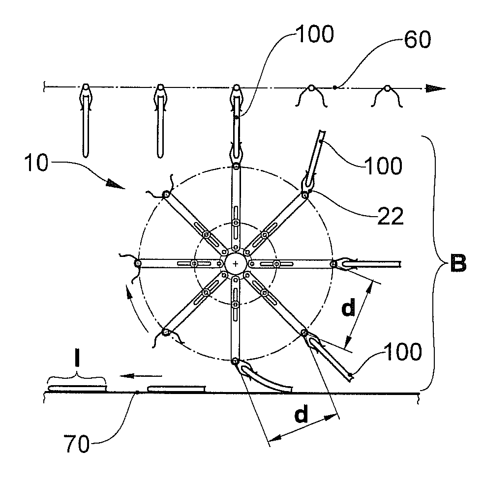
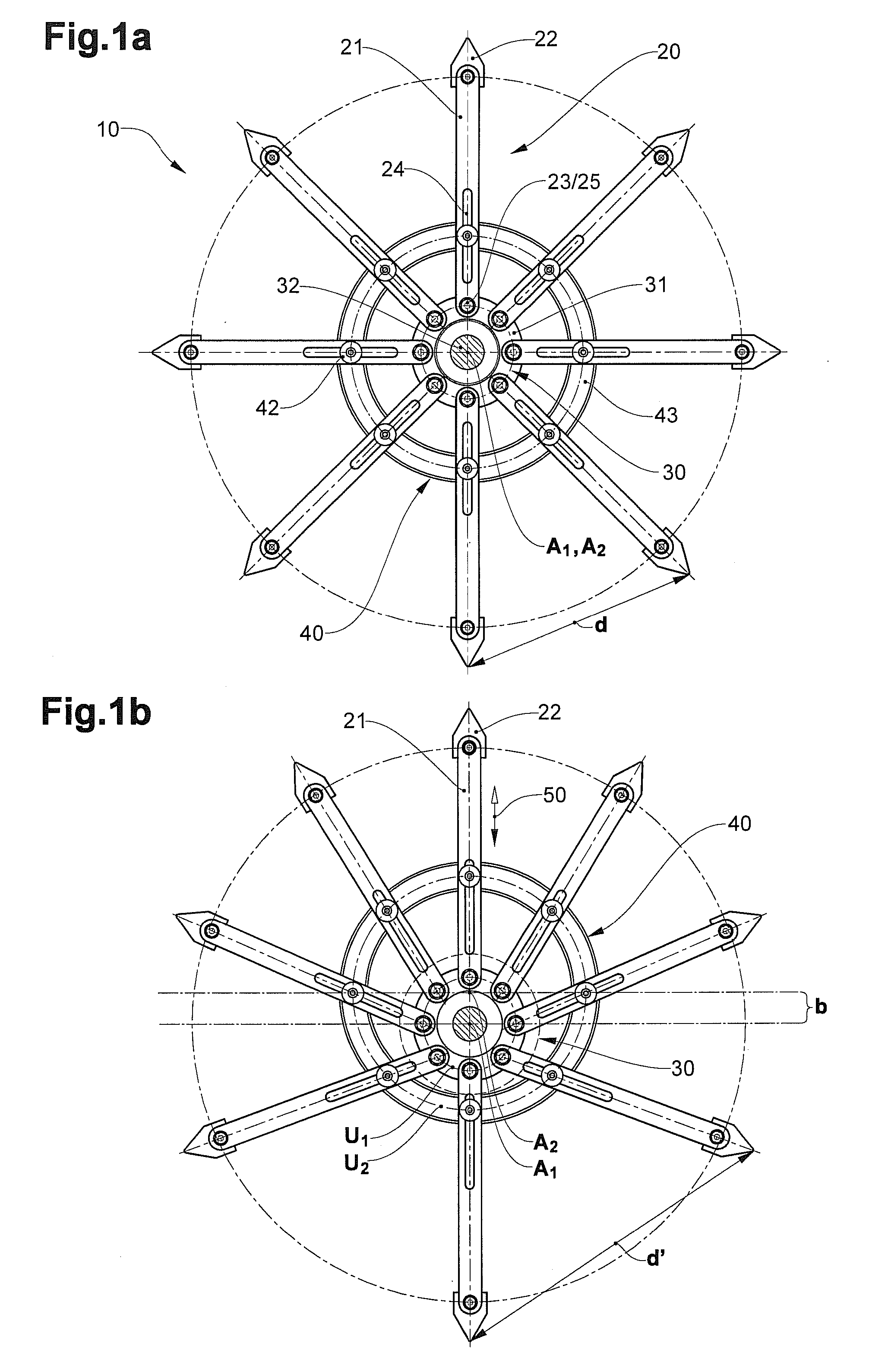
[0013]The invention is based on the changeable setting of the pivot position of an acting element which is arranged in a projecting manner via a lever on the tool drive arrangement, by way of an adjustable guide mechanism, with respect to an arbitrary reference point along the path. Depending on the setting of the guide mechanism, the lever, therefore, has different orientations at the same reference point, so that adjacent acting elements may have different distances in the respective region. Different distances of the acting elements may be set in a reference region by way of a suitable choice of the geometry, e.g. the lever length, the distance of the bearing points, the shape and position of the guide mechanism, without necessarily having to change the drive speed. The mechanics which are required for this as a rule may be realised in a simple manner, and in a manner which requires little maintenance, for example by way of displaceable guide elements running with the levers and / or displaceable but otherwise stationary guide mechanism or cam guide with several alternative guide paths. The achieved effect is particularly strong in curved parts of the movement path of the tools or of the bearing points of the levers assigned to them, wherein it may be the case of a concave or convex path shape.
[0017]Additionally to the adaptation of the distances at a certain reference location, the device according to the invention may be designed such that the distances between two acting elements, e.g. as with the state of the art according to EP-A 0 606 550, EP-A 0 606 549 or EP-A 0 606 555, are varied between a minimal distance and a maximal distance over the complete course of the revolving path, alone by way of the interaction of tool drive arrangement, tools and a fixedly set guide mechanism. With such a device, the minimal and maximal distance may be set in dependence on one another by way of the invention, so that the distance change is freely selectable within certain limits. This has advantages for example with the singularisation of products from an imbricate formation, or in the opposite case in which products are received individually and are to be condensed into an imbricate formation.
[0021]The guide elements may themselves be driven, in particular synchronously with the tool drive arrangement, for reducing the degrees of freedom. This then is particularly advantageous when the guide elements are displaceable relative to the tool. For example, analogously to the tool drive arrangement, a rotation body or a conveyor member may serve as guide element drive arrangement and on which the guide elements are mounted at defined, in particular constant distances.

Problems solved by technology

The different drives with the device according to WO 2007 / 147269, although permitting an adaptation of the processing distance, are however mechanically complicated and expensive in maintenance.

Method used


Image

  • Device and method for processing objects
  • Device and method for processing objects
  • Device and method for processing objects

Examples


Embodiment Construction

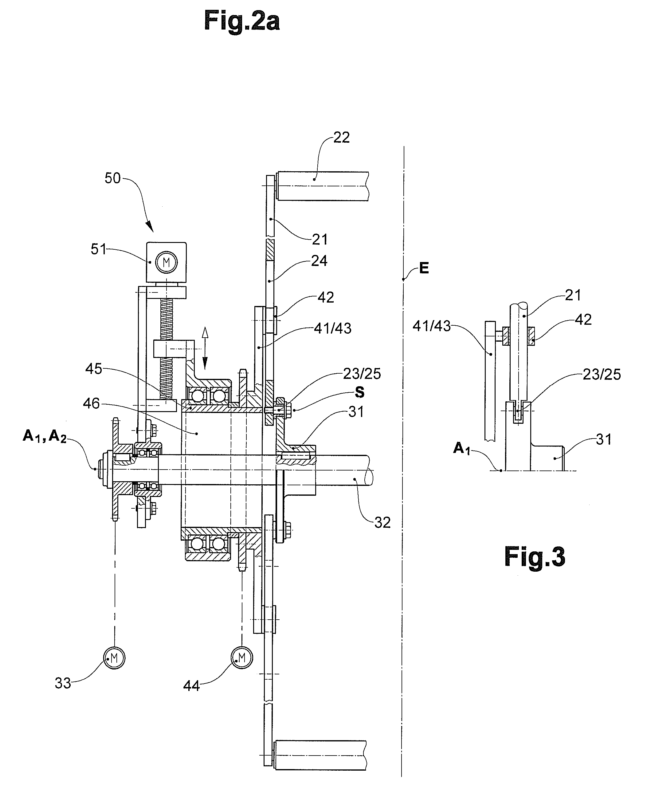
[0030]A first example of a processing device 10 according to the invention is represented in FIGS. 1a, 1b, 2a and 2b. This comprises several—here eight—tools 20 which are attached on a tool drive arrangement 30 on bearing points 23. The tools 20 in each case comprise at least one lever 21, which at its one end is connected in a pivotable manner to the tool drive arrangement 30 in the manner of a joint 25. The tools 20 moreover comprise an acting element 22 at the other lever end. The tool drive arrangement 30 here comprises a rigid rotation body 31 in the form of a wheel disk, which is connected to a drive shaft arranged coaxially to the rotation body 31. This may be set into rotation by a first drive 33, so that the bearing points 23 are moved along a circular revolving path U1. The pivot axes S of the levers 21 which go through the bearing points 23, run parallel to the drive shaft 32 or to its axis A1. The distances of adjacent bearing points 23 are constant along the periphery o...


PUM


Abstract

The invention relates to a device (10) and a method for processing objects (100, 110) with a plurality of tools (20), as well as with a tool drive arrangement (30). The tools (20) in each case comprise at least one lever (21) as well as an acting element (22) which may cooperate with the object (100, 110). The levers (21) are pivotably attached on tool drive arrangement (30) on bearing points (23) and may be driven along a closed revolving path by way of the movement of the tool drive arrangement (30). The acting elements (22) are distanced to the bearing point (23). The pivot position of the levers (231) relative to the tool drive arrangement (30) may be set in dependence on their position along the revolving path with a guide mechanism. According to the invention, the guide mechanism (40) is adjustable, wherein different distances (d, d′) of adjacent acting elements may be realised in a predefined reference region by way of the adjustment.

Description

BACKGROUND OF THE INVENTION[0001]1. Field of the Invention[0002]The invention lies in the field of processing or the transport of objects, in particular of printed products. It relates to a device and to a method according to the preambles of the claims, with which device or with which method the objects are processed with acting elements moved along a closed revolving path, and the distance of the acting elements is to be changed, for example, for adaptation to different formats or transfer locations.[0003]2. Description of Related Art[0004]With the processing of continuously conveyed objects, the distance of the tools used for processing must often be adapted to the distance of the objects in the conveyor flow to be supplied and / or to be released. Various solutions are known for this:[0005]Processing devices and transport devices for printed products are known from EP-A 0 606 55, EP-A 0 606 549 and EP-A 0 606 555, with which tools, e.g. grippers or stitching modules, are moved alo...

Claims


Application Information

Patent Timeline
IPC IPC(8): B65G25/00B65G47/86
CPCB26D1/42B42B4/00B65H2511/414B65H2511/20B65H2405/55B65H2405/531B65H29/06B65H29/003B65G29/00B65H2220/02B65H2220/11B65H2220/04B65H2220/01
Inventor STAUBER, HANS ULRICH
Owner FERAG AG
Learn More