Cutting Device for Agricultural Machines

Active Publication Date: 2015-10-29
CARL GERINGHOFF
View PDF20 Cites 22 Cited by
  • Summary
  • Abstract
  • Description
  • Claims
  • Application Information

AI Technical Summary

Benefits of technology

[0011]According to an embodiment of the invention, two adjacent knife bar sections are provided with a drive which drives the two knife bar sections with phase offset. The term phase offset refers to a drive action in which the knife bar sections are not movable at the same time in opposite directions or in the same direction. The drive action can be produced, for example, by one or more cranks, push rods, eccentric shafts, a hydraulic cylinder or an electric motor. The phase offset can be produced by appropriate mechanical devices and/or by means of electrical, electronic or hydraulic switching devices. Due to the phase offset, it is achieved that the peak load on the drive train, which occurs when a position of the knife blades relative to the mowing fingers, as counter cutting edges, is reached, always occurs only for one of two adjacent knife bar sections so that the peak load is halved and temporally offset by the phase offset for the respective knife bar section located in the corresponding position. As a result, the drive train can be relieved and designed to be more light weight.
[0012]According to an embodiment of the i

Problems solved by technology

In the case of forward travel with the cutting device into an upright crop stand, an

Method used


Image

  • Cutting Device for Agricultural Machines
  • Cutting Device for Agricultural Machines
  • Cutting Device for Agricultural Machines

Examples


Example

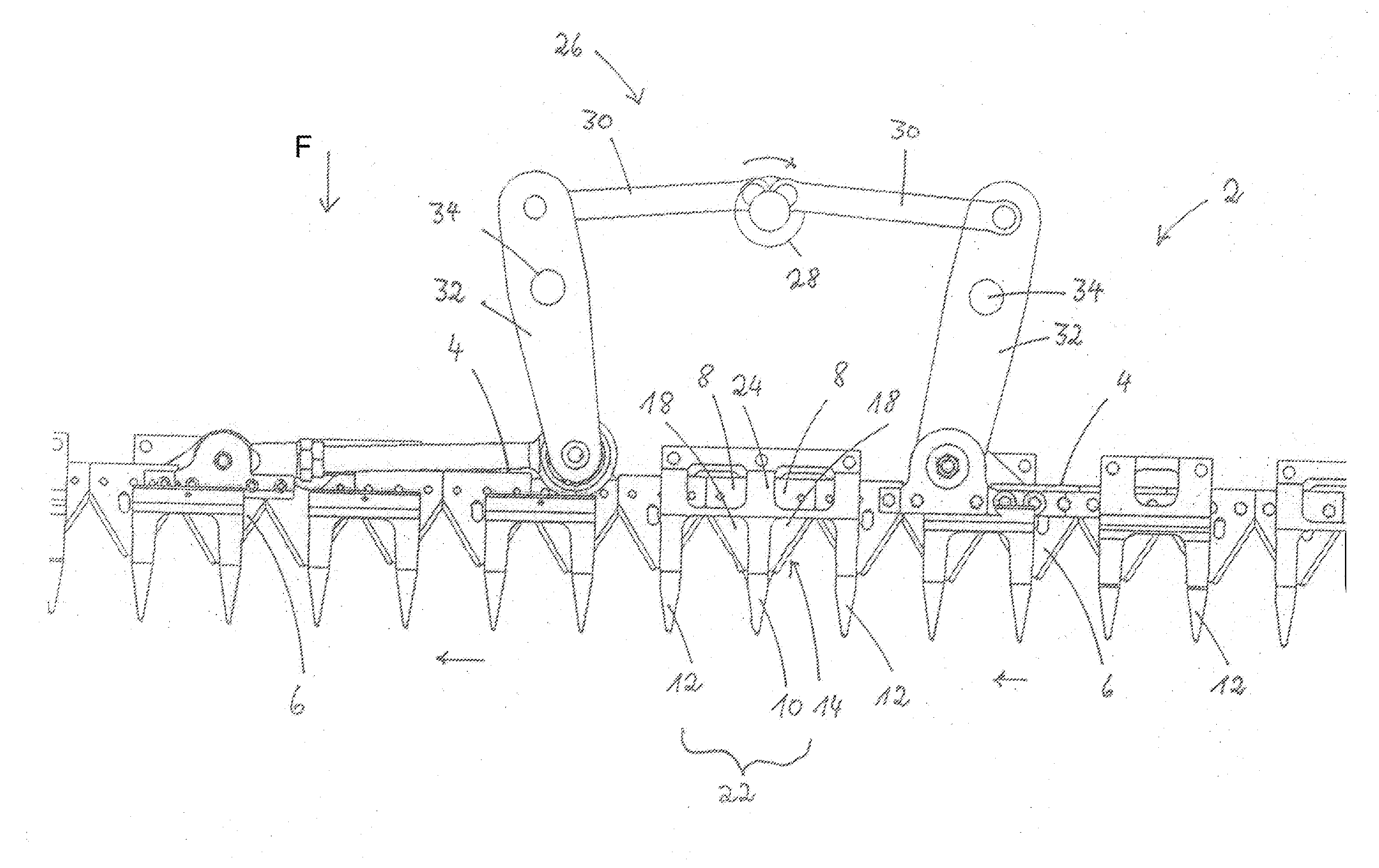
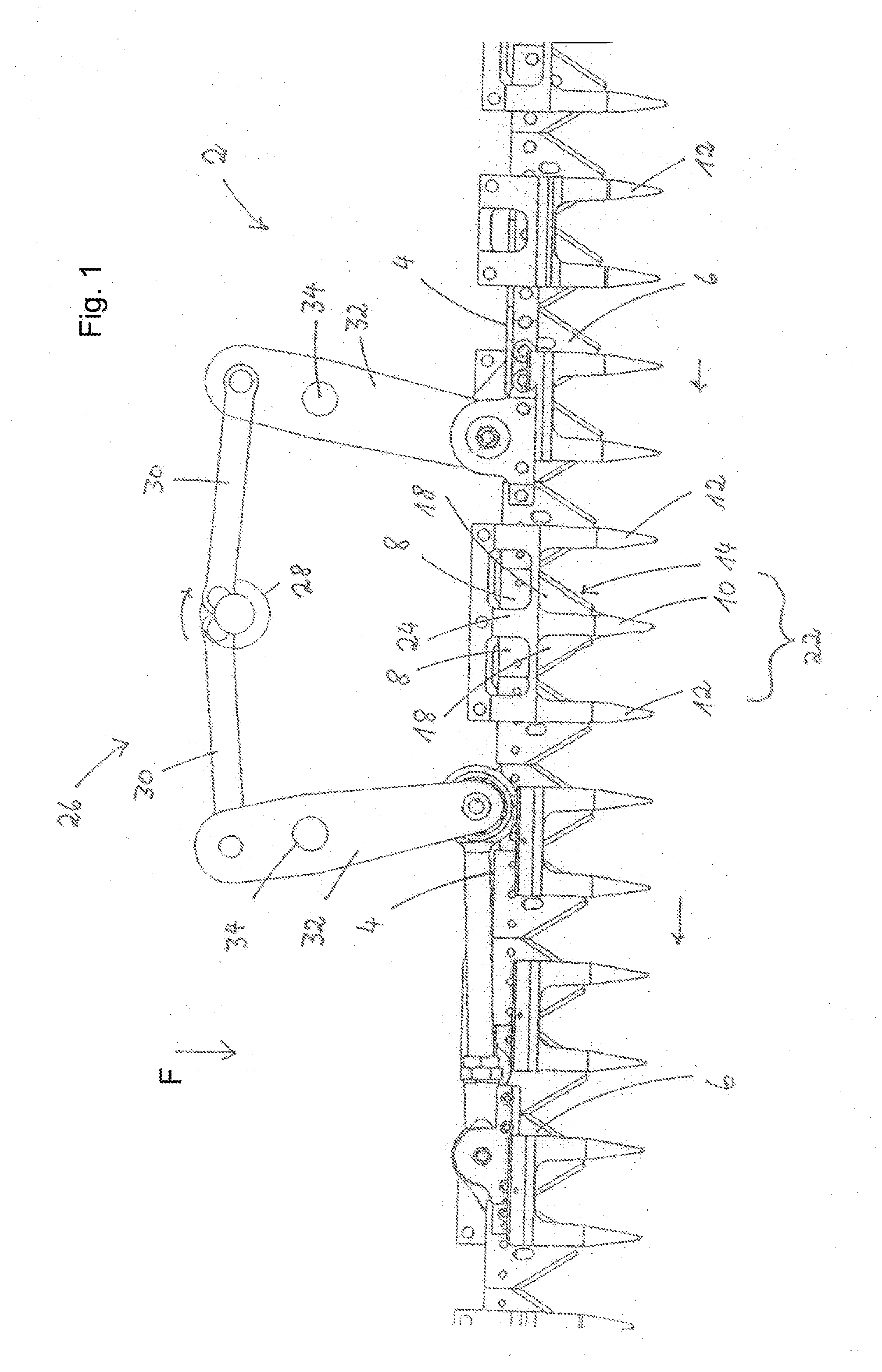
[0020]In FIG. 1, a basic configuration of a cutting device 2 is shown. In the embodiment, the cutting device has two knife bar sections 4 which are separated from one another in the central area of the drawing in the embodiment. In the swivel position in which the knife bar sections 4 are located in FIG. 1, the separation of the two knife bar sections 4 from one another is not visible since they are submerged with their mutually facing bar ends 8 and the outer knife blades 18 attached thereto in the central mowing finger 10. In addition to the central mowing finger 10, which is located in the area of a gap 22 resulting during a movement of the knife bar sections 4, the cutting device 2 has several additional mowing fingers 12, which function as counter cutting edges for the section knife blades 6 attached to the knife bar sections 4.

[0021]Beneath the mowing finger 10, a fixedly attached stationary knife blade 14 is located, which is covered in FIG. 1 by the outer knife blades 18. Th...


PUM


Abstract

An agricultural cutting device has knife bar sections with section knife blades. A drive with phase offset drives the knife bar sections at least temporarily in opposite directions. The section knife blades interact scissor-like with counter knives. The knife bar sections have adjacently positioned bar ends. When the knife bar sections move, a gap of varying size is formed between the bar ends. A mowing finger is arranged at the gap. A stationary knife blade with first cutting edges is arranged at the mowing finger. The first cutting edges are arranged adjacent to the mowing finger and extend at a slant relative to a forward travel direction of the cutting device so that the cutting edges have a V-shaped arrangement broadening in travel direction. The knife bar sections have an outer knife blade attached to the bar ends whose cutting edges extend parallel to the travel direction.

Description

BACKGROUND OF THE INVENTION[0001]The present invention relates to a cutting device for agricultural machines with several knife bar sections, which are driven so that they are at least temporarily movable in opposite directions and which extend over the working width of the cutting device, the knife blades of which, at the time of a stroke movement of the knife bar sections, interact in a scissor-like manner with counter knives attached fixedly to the cutting device.[0002]A cutting device of the aforementioned kind is known from DE 195 24 039 A1. These cutting devices can be used in particular with cutting assemblies for combine harvesters, but also in mowers for grass or for harvesting other agricultural stalk material.[0003]In DE 195 24 039 A1, it is disclosed to subdivide a cutting device into at least two cutting device portions in order to prevent vibrations and to avoid losses due to shaking. As a result of a phase shift of the driving frequency by 180°, the vibration generate...

Claims


Application Information

Patent Timeline
IPC IPC(8): A01D34/14
CPCA01D34/145A01D34/14A01D34/135A01D34/30
Inventor SURMANN, KLEMENSWEBERMANN, DIRKPOKRIEFKE, MICHAEL
Owner CARL GERINGHOFF
Why Eureka
Try Eureka