Wireless communication terminal apparatus and wireless communication method

a technology of wireless communication and terminal equipment, applied in the direction of wireless communication services, power management, signalling characterisation, etc., can solve the problems of not being able to calculate transmission power and phr of pusch with no ul, and the base station generally does not know an accurate pathloss value, so as to prevent such a mismatch

Active Publication Date: 2013-05-23
SUN PATENT TRUST
View PDF6 Cites 13 Cited by
  • Summary
  • Abstract
  • Description
  • Claims
  • Application Information

AI Technical Summary

Benefits of technology

[0032]According to the present invention, it is possible to prevent such a recognition mismatch that a radio communication terminal apparatus and a radio communication base station apparatus recognize reference formats of different UL grants.

Problems solved by technology

Therefore, a base station generally does not know an accurate pathloss value used for setting UL transmission power.
However, when there is no UL grant (transmission format; UL transmission bandwidth, MCS information or the like) to be reported from the base station to the terminal for all PUSCHs of a plurality of CCs (or a plurality of PUSCHs of CCs for reporting a PHR), it is not possible to calculate transmission power and PHR of a PUSCH with no UL grant (see FIG. 1).

Method used


Image

  • Wireless communication terminal apparatus and wireless communication method
  • Wireless communication terminal apparatus and wireless communication method
  • Wireless communication terminal apparatus and wireless communication method

Examples


embodiment 1

[0048]FIG. 3 is a block diagram illustrating a configuration of radio communication terminal apparatus (hereinafter, simply referred to as “terminal”) 100 according to Embodiment 1 of the present invention. Hereinafter, the configuration of terminal 100 will be described with reference to FIG. 3.

[0049]Radio reception processing section 102 receives an OFDM signal transmitted from a base station via antenna 101, applies predetermined radio reception processing such as down-conversion, A / D conversion to the received OFDM signal and outputs the received OFDM signal to OFDM demodulation section 103.

[0050]OFDM demodulation section 103 removes a guard interval from the received OFDM signal outputted from radio reception processing section 102, applies discrete Fourier transform (DFT) to transform the OFDM signal into a frequency-domain signal. OFDM demodulation section 103 applies frequency-domain equalization (FDE) to each frequency-domain component, removes signal distortion, outputs a ...

embodiment 2

[0096]Embodiment 2 of the present invention will describe a case where Multiple Input Multiple Output (MIMO) transmission is performed using a CC that transmits a PHR. However, the configurations of a terminal and a base station according to Embodiment 2 of the present invention are similar to those shown in FIG. 3 and FIG. 5 of Embodiment 1 and only some functions thereof are different, and therefore the different functions will be described using FIG. 3 and FIG. 5. The following description will be given assuming a case where parameter information used to calculate a transmission power headroom of an uplink channel that transmits a PHR is used to calculate transmission power or a transmission power headroom of another uplink channel that transmits no UL grant.

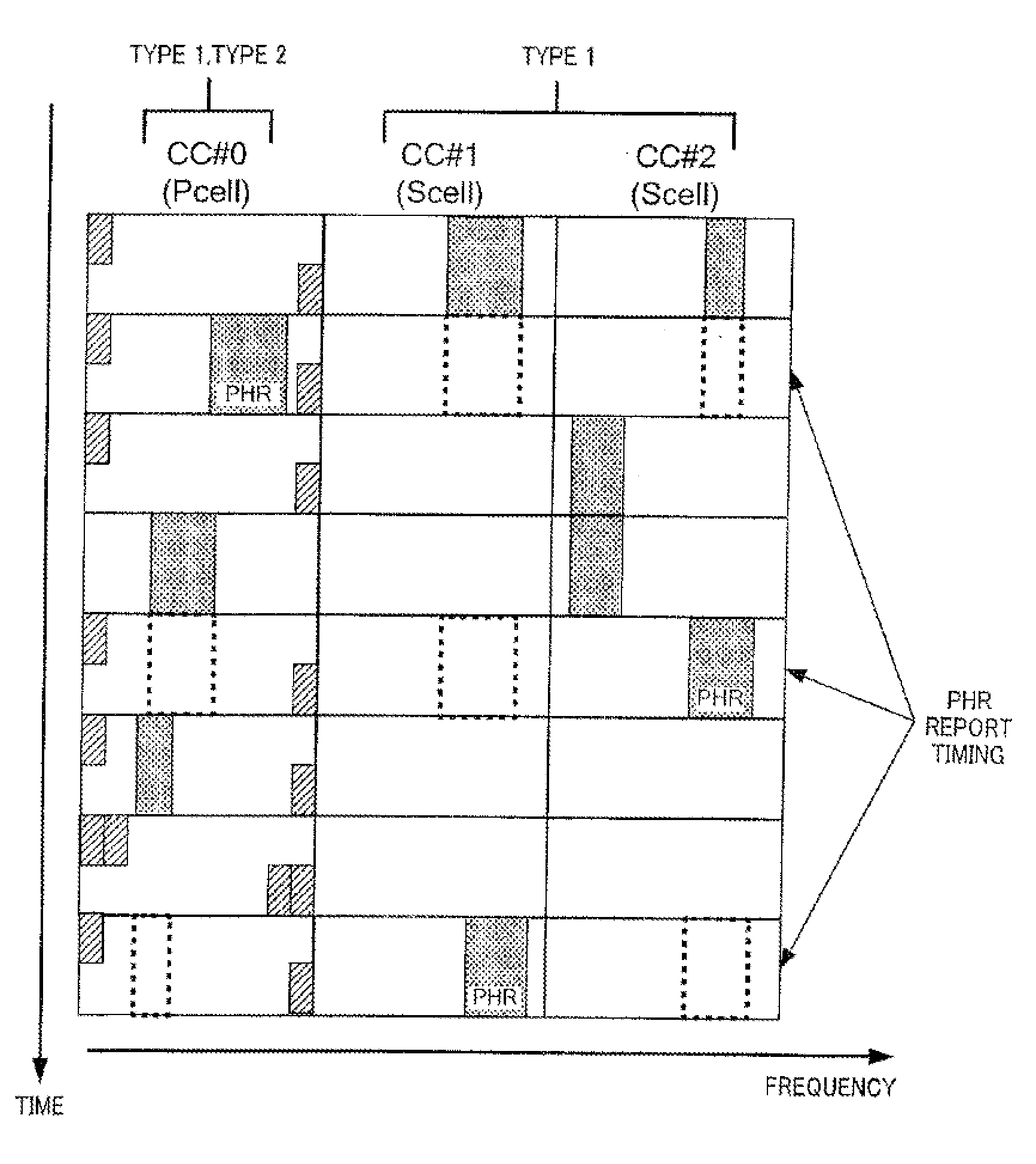
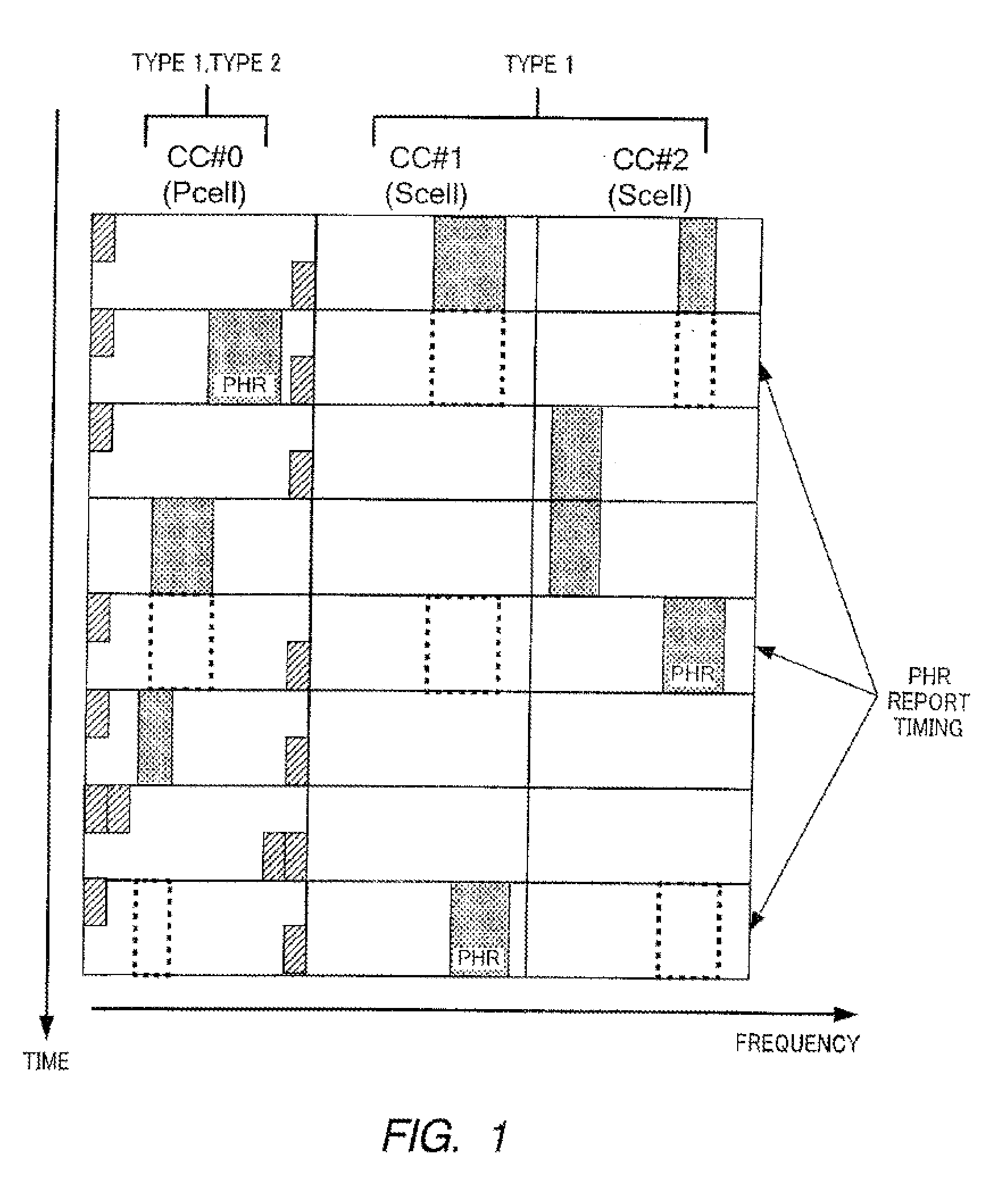
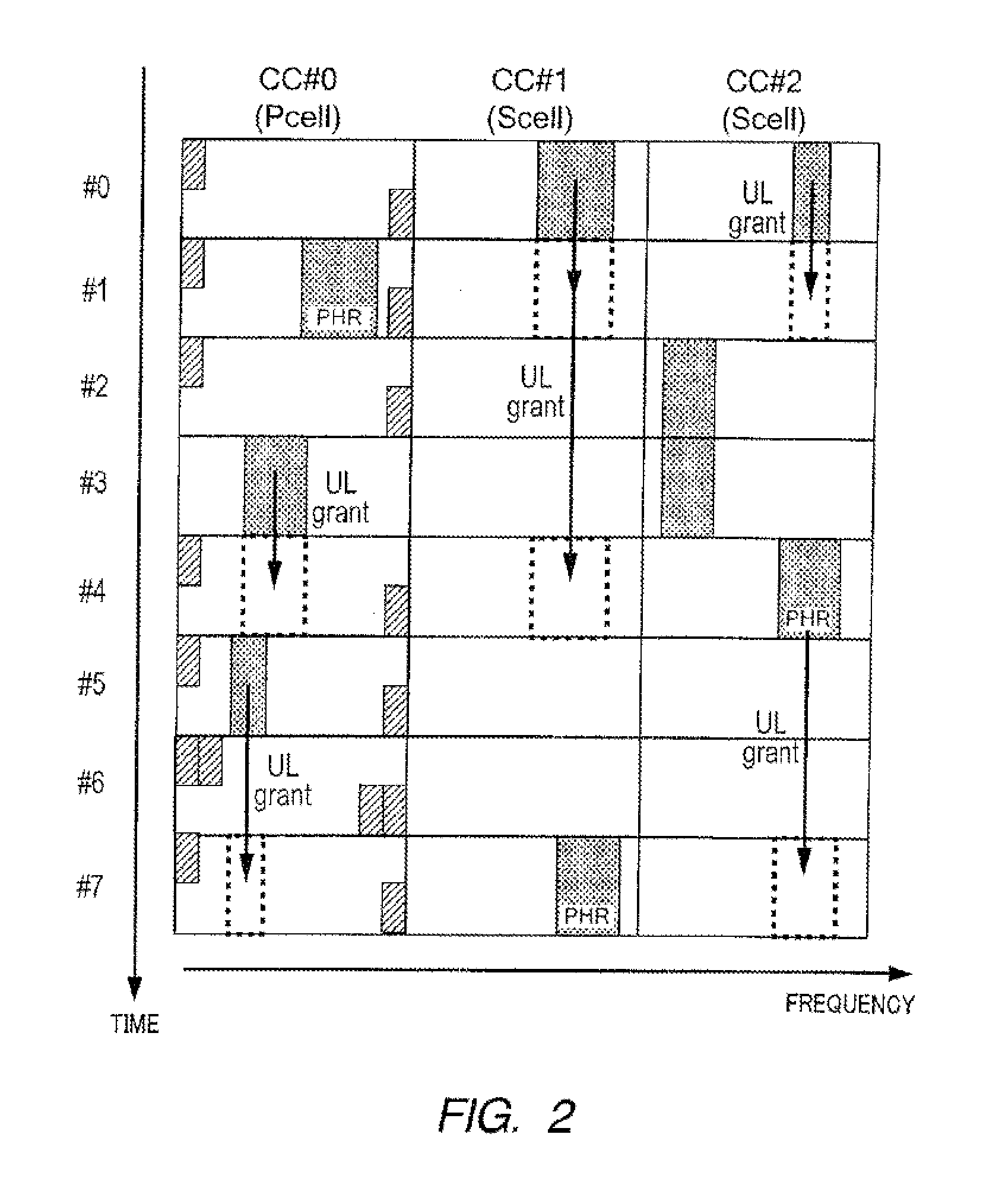
[0097]Operation of the PHR calculation section of the terminal according to Embodiment 2 of the present invention will be described using FIG. 11. FIG. 11 assumes a case where carrier aggregation is configured of three CCs, a...


PUM


Abstract

Provided are a wireless communication terminal apparatus and a wireless communication method that can preclude the recognition mismatch in which the reference formats of different UL grants are recognized between the wireless communication terminal apparatus and a wireless communication base station apparatus. For the PHR calculation of a PUSCH in a CC in which no UL grant is present, a UL grant, which was used for calculating the PHR in another CC having the same subframe number as the PUSCH, is used. For example, as to a subframe number=#1, the UL grant of CC #0 is used for calculating the PHR of CC #2 in which no UL grant is present.

Description

TECHNICAL FIELD[0001]The present invention relates to a radio communication terminal apparatus and a radio communication method for reporting a PHR (power headroom).BACKGROUND ART[0002]In 3GPP (3rd Generation Partnership Project), studies are being carried out on LTE-advanced. In LTE-advanced, the introduction of a band extension technique called “carrier aggregation” is under study.[0003]In carrier aggregation, a plurality of component carriers (CCs), one CC being composed of 20 MHz, are bundled to aggregate a plurality of carriers and an approach for realizing high-speed transmission is adopted for downlink (DL) and uplink (UL) channels. In LTE-advanced, studies are being carried out with the introduction of five CCs, that is, band extension of up to 100 MHz in view.[0004]In line with this trend, a transmission power control method targeting UL carrier aggregation is also being studied at the same time. In the design of UL transmission power control, a plurality of matters as show...

Claims


Application Information

Patent Timeline
Patent Type & Authority Applications(United States)
IPC IPC(8): H04W72/04
CPCH04L5/001H04L5/0053H04L5/0094H04W52/16H04W52/34H04L1/0031H04L1/1607H04W72/0473H04W52/365H04W52/262H04W52/242H04W72/23H04W52/146H04W52/367
Inventor TAKAOKA, SHINSUKEIWAI, TAKASHI
Owner SUN PATENT TRUST
Why Eureka
Try Eureka