Electrical device with a clamshell electrical connector

a technology of electrical connectors and clamshells, which is applied in the direction of coupling device details, coupling device connections, instruments, etc., can solve the problem of not being convenient to manually close the cover member on the base member, and achieve the effect of convenient us

Active Publication Date: 2013-05-23
HON HAI PRECISION IND CO LTD
View PDF12 Cites 41 Cited by
  • Summary
  • Abstract
  • Description
  • Claims
  • Application Information

AI Technical Summary

Benefits of technology

[0006]An object of the present invention is to provide an electrical connector easy to use and an electrical device using the same.

Problems solved by technology

However, it is not convenient to manually close said cover member on said base member when said cover member of the flip-type electrical connector needs to rotated to its closed position.

Method used


Image

  • Electrical device with a clamshell electrical connector
  • Electrical device with a clamshell electrical connector
  • Electrical device with a clamshell electrical connector

Examples


Embodiment Construction

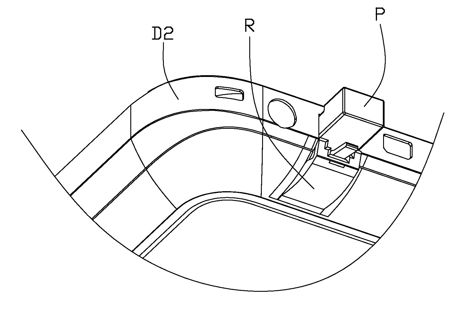
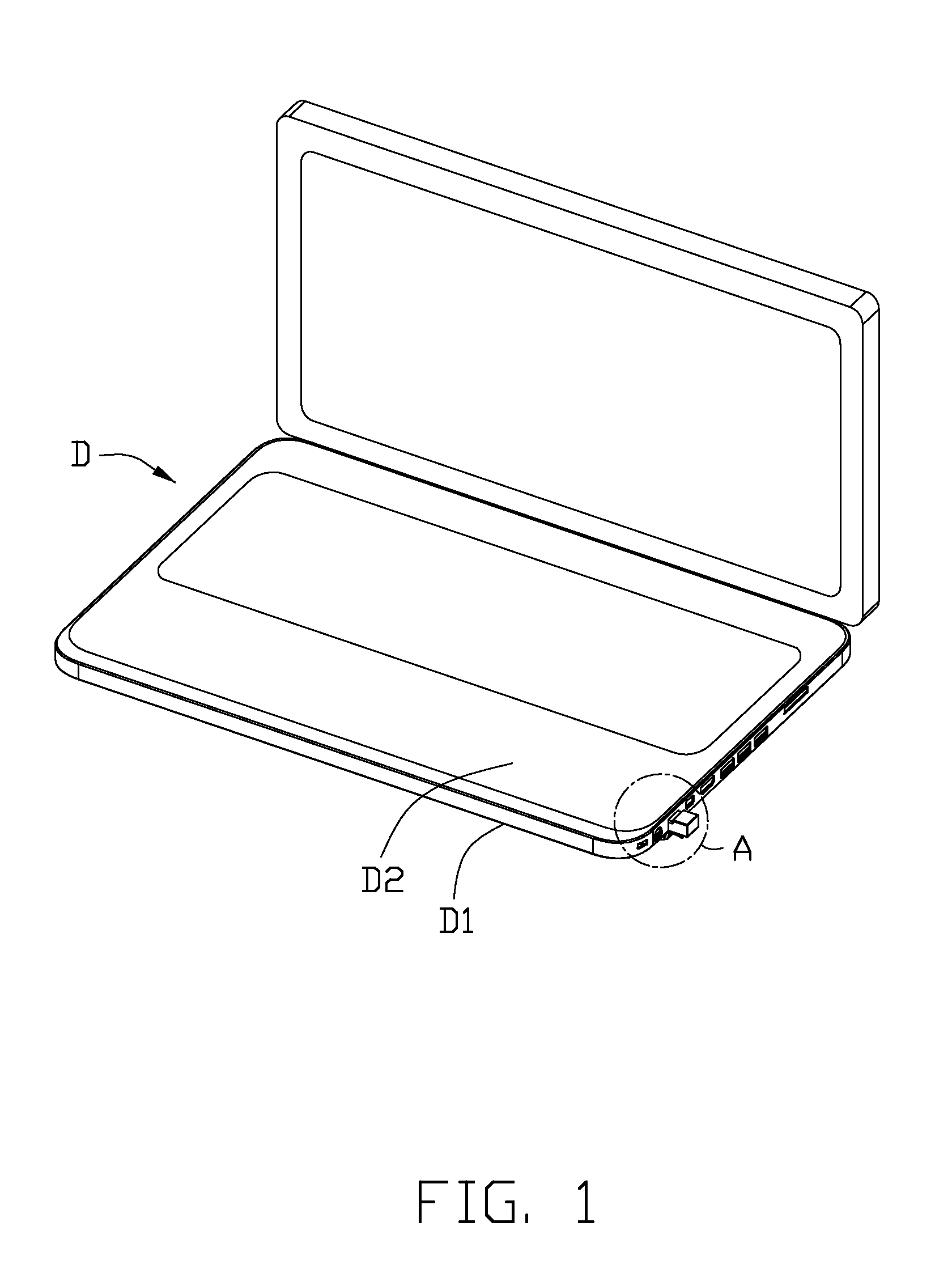
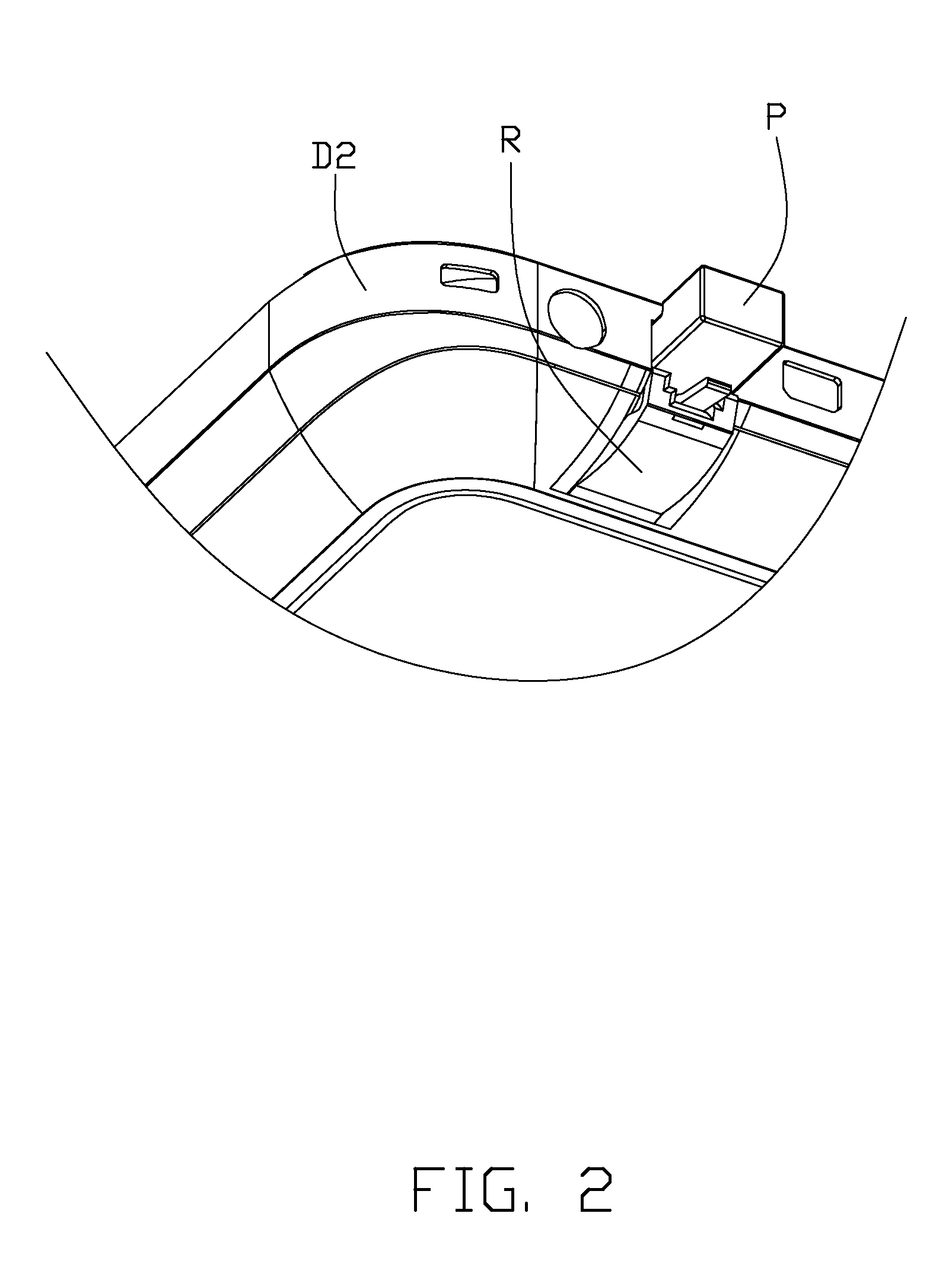
[0017]Reference will now be made to the drawing figures to describe a preferred embodiment of the present invention in detail. Referring to FIGS. 1 to 3 illustrate an electrical device D such as Notebook, includes a base system with a mother board 6 (shown in FIG. 6). The base system of the electrical device D comprises a lower shell D1 located at a bottom thereof and an upper shell D2 covering above the lower shell D1, thereby defining a mounting space to receive said mother board 6 and other electrical components (not shown). The base system further defines an electrical connector R or receptacle therein to be inserted with a mating connector P or a cable plug with P. The electrical device will be described hereinwith. In this preferred embodiment combination with FIG. 6, the mother board 6 is mounted in the upper shell D2, the electrical connector R is sunk in the mother board 6 in an upside downward pattern. Alternatively, the invention is not limited in said pattern.

[0018]Refer...


PUM


Abstract

An electrical device includes an upper shell facing a user, a lower shell engaged with the upper shell to commonly define a mounting space, a mother board mounted in the mounting space, a receptacle portion and a rotating cover rotating about the receptacle portion. The upper shell defines a first opening for an insertion of a mating plug. The mother board defines a notch, wherein the receptacle portion is holding conductive terminals therein, the receptacle portion is assembled in the notch of the mother board and between the mother board and the upper shell. Wherein the lower shell defines a second opening, the rotating cover is received in the second opening and a front portion of the rotating cover is actuated in to the first opening of the receptacle portion.

Description

BACKGROUND OF THE INVENTION[0001]1. Field of the Invention[0002]The present invention relates to an electrical connector and an electrical device with the same, and more particularly to a clamshell electrical connector.[0003]2. Description of the Related Art[0004]U.S. Pat. No. 5,679,013 issued to Ma et al. on Oct. 21, 1997, discloses an open / close type electrical connector including: a base member having an upper face defining an aperture; a cover member for opening and closing said aperture of said base member; means defining a receiving face, disposed in said base member, for receiving a counter electrical connector having a rectangular parallelepiped shape; at last one terminal member, disposed in said based member, and being elastically in contact with a terminal of the counter electrical connector, said cover member being pivotally supported in end portion of said base member for rotation between an opened position and a closed position, said cover member defining thereby an ax...

Claims


Application Information

Patent Timeline
Patent Type & Authority Applications(United States)
IPC IPC(8): H01R13/447
CPCG06F1/1656H01R2201/06H01R13/447
Inventor WANG, JI-CHENG
Owner HON HAI PRECISION IND CO LTD
Why Eureka
Try Eureka