
System and Method for Physically Based Curve Editing

a technology of physical based curves and editing methods, applied in the field of system and method for physically based curve editing, can solve the problems of difficult prediction of editing operations involving the manipulation of the inability to intuitively operate by most users, and the inability to manipulate the control points of the curve. achieve the effect of finer granularity

Active Publication Date: 2013-05-23
ADOBE INC
View PDF5 Cites 13 Cited by
  • Summary
  • Abstract
  • Description
  • Claims
  • Application Information

AI Technical Summary

Benefits of technology

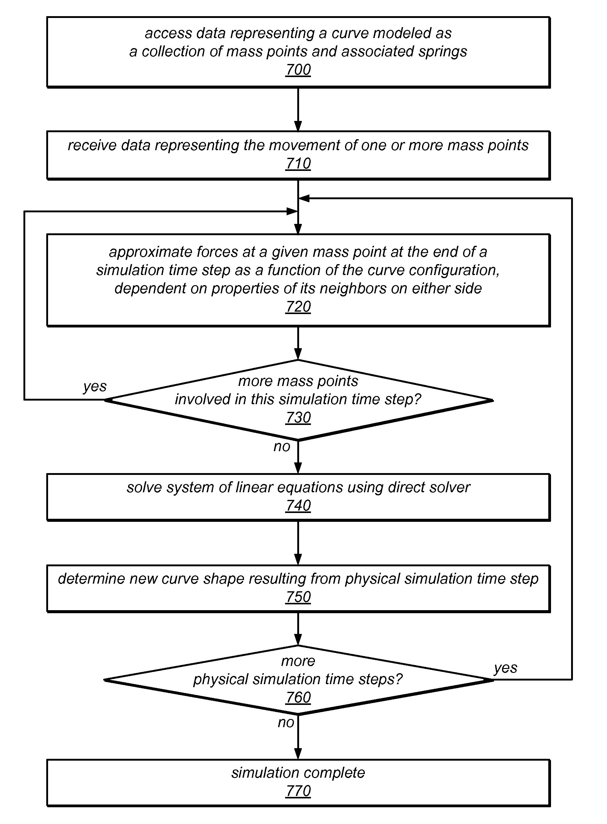
The patent describes a system and method for editing curves using physical simulations. The system generates a model of the curve by adding or removing mass points and distributing the mass of the curve among them based on the distances between the mass points. The system can also adjust the position of the mass points based on the new shape of the curve resulting from the editing operation. The technical effect of this system is that it allows for precise and real-time editing of curves by simulating the forces acting on the mass points and adjusting their positions accordingly.

Problems solved by technology

Editing by manipulation of such control points is not an intuitive operation for most users, since the control points are not on the curve.
Furthermore, curve models based on such control points have no physical basis (i.e. the curve models do not model physical properties associated with manipulation of the curve).
Because manipulation of the control points in these curve models does not reflect physical properties of curve editing operations, users may not have an intuitive feel for how changes to the control points affect the curve itself (e.g., its shape) Therefore, the results of editing operations that involve the manipulation of the control points of a curve can be difficult to predict.

Method used


Image

  • System and Method for Physically Based Curve Editing
  • System and Method for Physically Based Curve Editing
  • System and Method for Physically Based Curve Editing

Examples


example implementations

[0107]FIG. 16 illustrates a curve editing module that may implement one or more of the physically based curve editing techniques described herein. Curve editing module 1620 may, for example, implement one or more of a curve model generator, a physical simulator for simulating curve editing operations, a linear system solver, a melting tool, or other components to implement the techniques described herein. In various embodiments, curve editing module 1620 may be a standalone module, or may be a module of an image editing application (e.g., any application that can be used to draw or edit images, including digital drawing / painting programs, photo editing programs, games, etc.) FIG. 16, described in detail below, illustrates an example computer system on which embodiments of curve editing module 1620 may be implemented.

[0108]As illustrated in FIG. 16, curve editing module 1620 may receive as input one or more digital images 1610, some of which may include one or more continuous curves....


PUM


Abstract

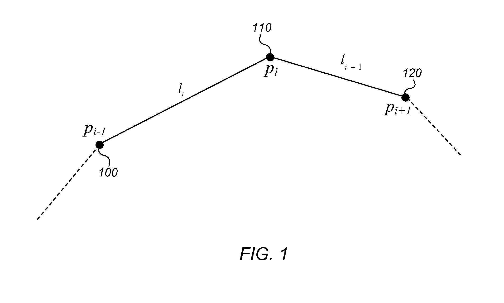
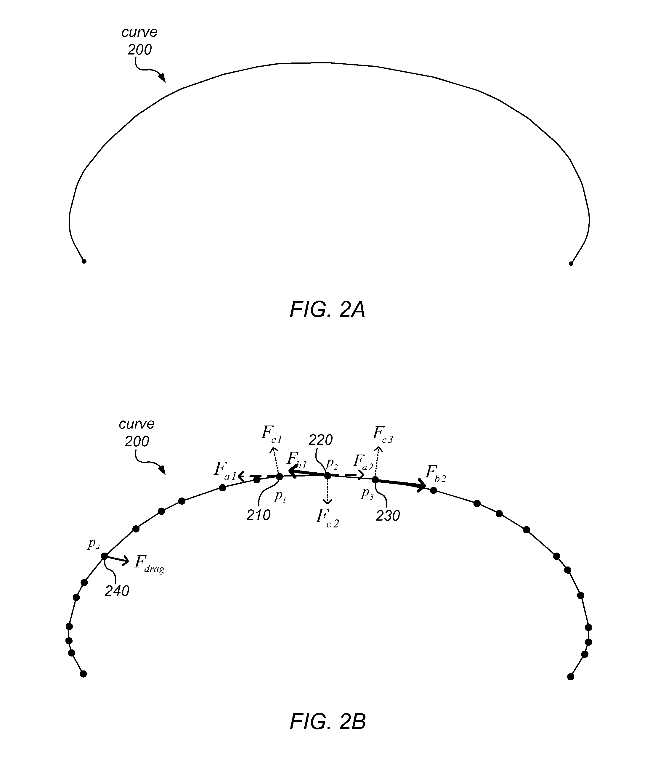
A curve editor may model a continuous curve as a finite collection of discrete mass points (among which the curve's mass is distributed) and associated springs. The springs may include damped axial springs between pairs of consecutive mass points, and damped bending springs representing interactions between sets of three consecutive mass points. In response to manipulation of the curve at various mass points, the curve editor may determine new positions and / or velocities of one or more mass points using a real time physical simulation of the spring forces acting at mass points involved in the editing operation. The simulation may be dependent on viscous drag forces and / or on constraints applied to individual mass points, angles defined by consecutive mass points, or an absolute direction of a segment between two mass points. Mass points may be added to or removed from the model by adaptive resampling, and the mass redistributed accordingly.

Description

PRIORITY INFORMATION[0001]This application claims benefit of priority of U.S. Provisional Application Ser. No. 61 / 384,171 entitled “System and Method for Physically-Based Curve Editing” filed Sep. 17, 2010, the content of which is incorporated by reference herein in its entirety.BACKGROUNDDescription of the Related Art[0002]Current techniques for editing curves are typically based on non-physical curve models, such as Bézier curves or NURBS (Non-Uniform Rational B-Splines). These curve models may include anchor points on a given curve and control points that are not on the curve itself, but are outside of and associated with the curve. To edit a curve modeled using anchor points and control points, a user may manipulate one or more of the control points.[0003]Editing by manipulation of such control points is not an intuitive operation for most users, since the control points are not on the curve. Furthermore, curve models based on such control points have no physical basis (i.e. the...

Claims


Application Information

Patent Timeline
Patent Type & Authority Applications(United States)
IPC IPC(8): G06G7/48
CPCG06T11/203
Inventor HADAP, SUNILBOROSAN, PETER
Owner ADOBE INC
Learn More