
Inkjet recording apparatus

a recording apparatus and inkjet technology, applied in the direction of printing and inking apparatus, can solve the problem of reducing the amount of ejecting ink compared to the normal amount, and achieve the effect of suppressing residual vibration to ejecting ink

Inactive Publication Date: 2013-05-30
RISO KAGAKU CORP
View PDF15 Cites 10 Cited by
  • Summary
  • Abstract
  • Description
  • Claims
  • Application Information

AI Technical Summary

Benefits of technology

The present invention is an inkjet printing device that can effectively reduce the vibration when ink is ejected. This is accomplished using a cancel pulse, which suppresses the residual vibration.

Problems solved by technology

If a cancel pulse intended to suppress residual vibration is applied to such an ink, there occurs such trouble that the amount of ejected ink is reduced compared to the normal amount.

Method used


Image

  • Inkjet recording apparatus
  • Inkjet recording apparatus
  • Inkjet recording apparatus

Examples


Embodiment Construction

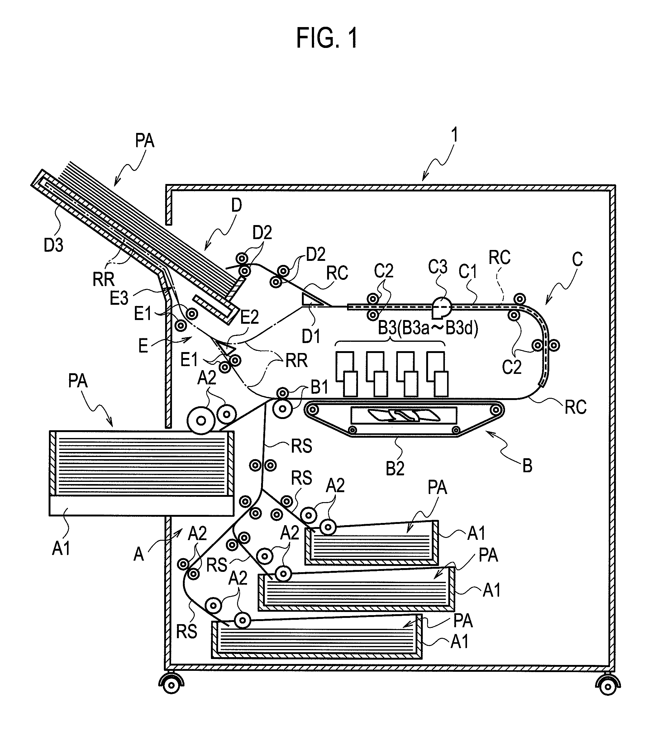
[0024]Several embodiments of the present invention will be explained below with reference to the accompanying drawings. FIG. 1 is a diagram showing an outline of a configuration of an inkjet printer according to an embodiment of the present invention. As shown in FIG. 1, an inkjet printer (inkjet recording apparatus) 1 of the present embodiment includes a sheet feeder A, a printer B, a dryer C, a sheet discharge unit D, and a reverse unit E.

[0025]The sheet feeder A feeds a recording sheet PA. The sheet feeder A is arranged at the uppermost stream side of the transfer path indicated by the thick line of FIG. 1. The sheet feeder A includes a plurality of sheet feed tables A1 and a plurality of pairs of sheet feed rollers A2. The sheet feed roller A2 transfers the recording sheet PA from any of the sheet feed tables A1 through a sheet feed path RS that follows the sheet feed table A1 and feeds the recording sheet PA to the printer B.

[0026]The printer B prints an image on the recording ...


PUM


Abstract

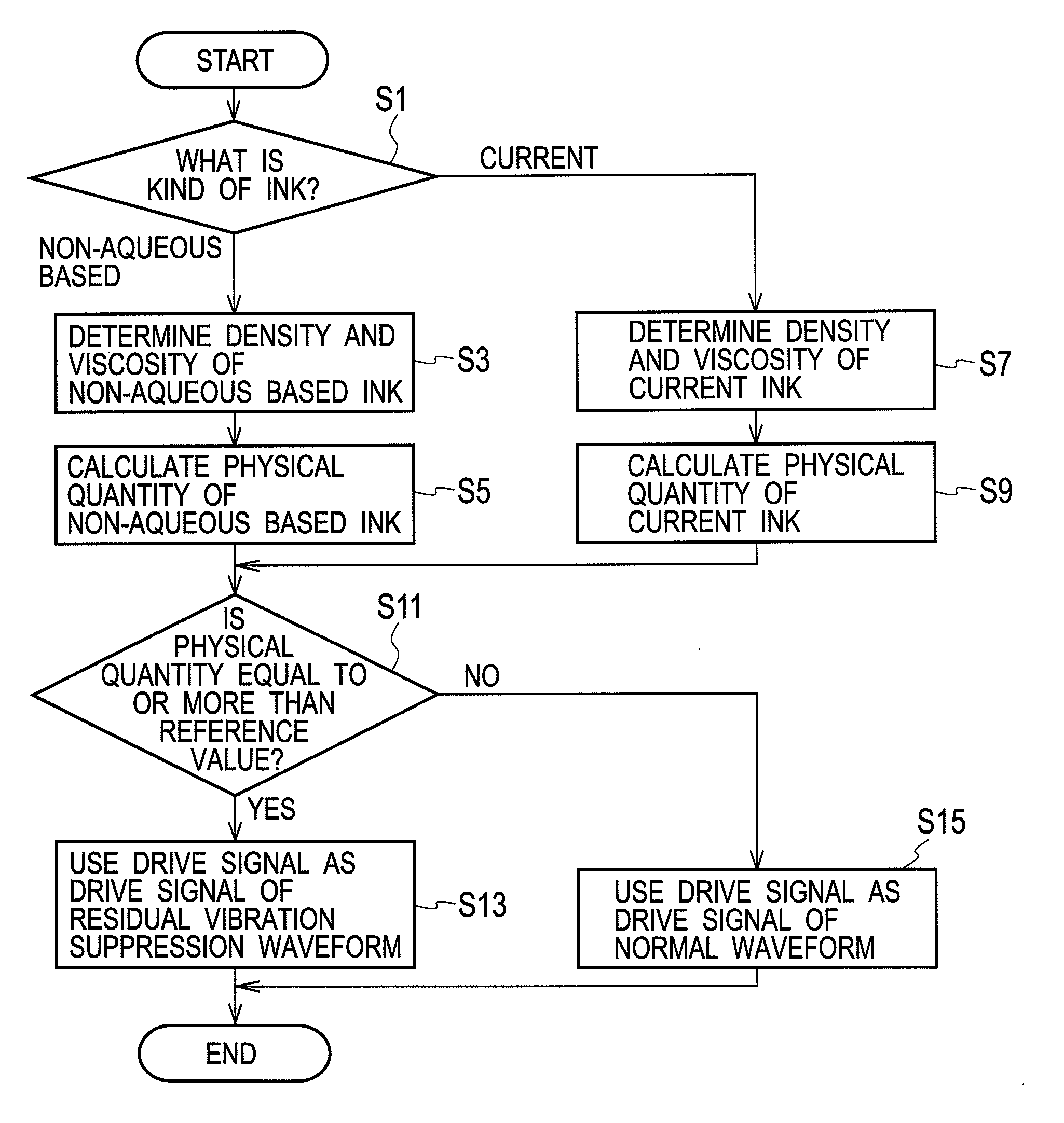
When a non-aqueous ink having a high density is used, a physical quantity defined as “density / viscosity” is equal to or more than a reference value, and therefore printing on a recording sheet is performed using a drive signal with a waveform for suppressing a residual vibration of the ink. Likewise, as to an ink having a low density, when the viscosity of the ink is low, the physical quantity is equal to or more than the reference value, and therefore printing on a recording sheet is performed using the drive signal with a waveform for suppressing a residual vibration of the ink. On the contrary, when the physical quantity is less than the reference value, printing on a recording sheet is performed using the drive signal with a normal waveform.

Description

BACKGROUND OF THE INVENTION[0001]1. Technical Field[0002]The present invention relates to an inkjet recording apparatus that ejects an ink within an ink chamber from a nozzle communicated with the ink chamber by increasing or decreasing the pressure on the ink within the ink chamber.[0003]2. Background Arts[0004]In the inlet recording apparatus, an ink is ejected from a nozzle by applying a pressure to the ink within the ink chamber by contracting the ink chamber provided at an inkjet head after expanding by a drive pulse for a predetermined period of time. At this time, if a residual vibration occurs in the ink that remains within the ink chamber, it is not possible to apply a sufficient pressure to the ink when ejecting the ink from the ink chamber the next time, and thus the ink ejection performance is reduced. Therefore, after ink is ejected, the ink chamber is expanded (or contracted) after contracting (or expanding) for a fixed period of time by a cancel pulse to cancel the ab...

Claims


Application Information

Patent Timeline
Patent Type & Authority Applications(United States)
IPC IPC(8): B41J2/045
CPCB41J2/0454B41J2/04525B41J2/04543B41J2/04551B41J2202/12B41J2/04571B41J2/04581B41J2/04588B41J2202/10B41J2/04563
Inventor NISHIMURA, ASAYOENDO, TOSHIHIRO
Owner RISO KAGAKU CORP
Learn More