Electrical switching apparatus with overvoltage protection

Active Publication Date: 2013-05-30
EATON INTELLIGENT POWER LIMITED
View PDF3 Cites 15 Cited by
  • Summary
  • Abstract
  • Description
  • Claims
  • Application Information

AI Technical Summary

Benefits of technology

[0020]For a subsequent overvoltage between the first terminal and the neutral conductor prior to the failure of the first fused varistor and prior to failure of the second varistor, the overvoltage detection circuit may be structured to respond to an overvoltage between the first terminal and the neutral conductor, energize the trip coil and cause the trip mechanism to trip open the separable contacts.
[0021]The first fused varistor may comprise a fuse electrically conducted in series with a varistor between the first terminal and the neutral conductor; t

Problems solved by technology

Thus, the heat generated in the varistor by the flow of abnormal leakage current therethrough will also indirectly heat the therm

Method used


Image

  • Electrical switching apparatus with overvoltage protection
  • Electrical switching apparatus with overvoltage protection

Examples


Embodiment Construction

[0025]As employed herein, the term “number” shall mean one or an integer greater than one (i.e., a plurality).

[0026]As employed herein, the statement that two or more parts are “connected” or “coupled” together shall mean that the parts are joined together either directly or joined through one or more intermediate parts. Further, as employed herein, the statement that two or more parts are “attached” shall mean that the parts are joined together directly.

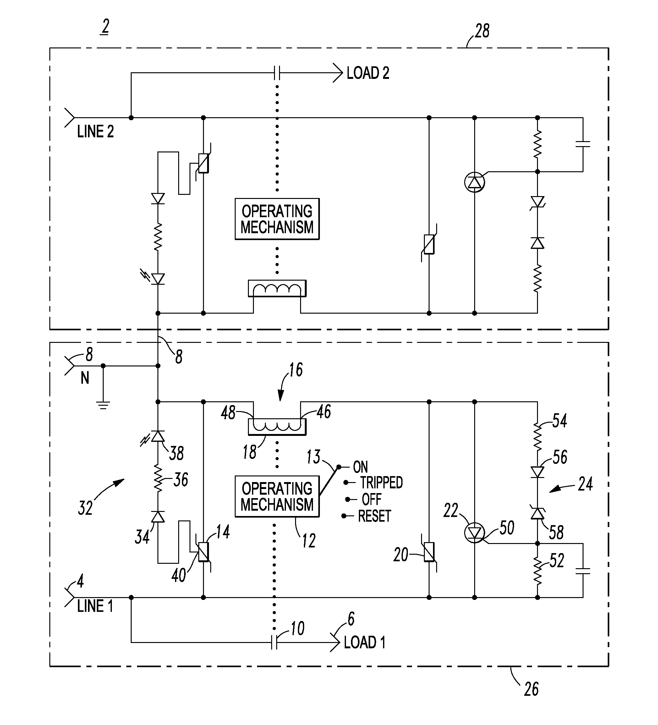
[0027]The disclosed concept is described in association with a two-pole surge device and circuit interrupter, although the disclosed concept is applicable to a wide range of electrical switching apparatus having any number of poles or phases.

[0028]Referring to FIG. 1, an electrical switching apparatus, such as the example two-pole circuit interrupter 2, includes a first terminal (LINE 1) 4, a second terminal (LOAD 1) 6, a neutral conductor (N) 8, separable contacts 10 electrically connected between the first terminal 4 and the secon...


PUM


Abstract

An electrical switching apparatus includes a first terminal, a second terminal, a neutral conductor, separable contacts electrically connected between the terminals, an operating mechanism to open and close the contacts, a fused varistor electrically connected between the first terminal and the neutral conductor; and a trip mechanism including a trip coil cooperating with the operating mechanism to trip open the contacts. A second varistor is electrically connected in series with the trip coil between the first terminal and the neutral conductor. A thyristor is electrically connected in parallel with the second varistor. An overvoltage detection circuit is electrically interconnected with and causes the thyristor to energize the trip coil and cause the trip mechanism to trip open the contacts responsive to overvoltage between the first terminal and the neutral conductor.

Description

BACKGROUND[0001]1. Field[0002]The disclosed concept pertains to electrical switching apparatus and, more particularly, to circuit breakers, such as, for example, circuit breakers including overvoltage and surge protection.[0003]2. Background Information[0004]Circuit breakers are generally old and well known in the art. Circuit breakers are used to protect electrical circuitry from damage due to an overcurrent condition, such as an overload condition or a relatively high level short circuit or fault condition. In small circuit breakers, commonly referred to as miniature circuit breakers, used for residential and light commercial applications, such protection is typically provided by a thermal-magnetic trip device. This trip device includes a bimetal, which heats and bends in response to a persistent overcurrent condition. The bimetal, in turn, unlatches a spring powered operating mechanism, which opens the separable contacts of the circuit breaker to interrupt current flow in the pro...

Claims


Application Information

Patent Timeline
IPC IPC(8): H02H3/20
CPCH02H3/20H02H3/06H02H3/04
Inventor NATILI, THOMAS E.STIFFLER, DAVID W.MATTOCKS, JOSHUA P.
Owner EATON INTELLIGENT POWER LIMITED
Why Eureka
Try Eureka