System for optimizing latency in an avb network

a technology of latency optimization and avb network, which is applied in the field of optimizing the latency of the avb network, can solve the problems of increasing the total time that elapses, time delay, and increasing the time it takes for the data stream to be transmitted

Active Publication Date: 2013-05-30
HARMAN INT IND INC
View PDF21 Cites 44 Cited by
  • Summary
  • Abstract
  • Description
  • Claims
  • Application Information

AI Technical Summary

Benefits of technology

[0005]A network communication system may include a talker that is configured to transmit a data stream to a plurality of listeners configured to receive the data stream over a network, such as an Ethernet Audio / Video Bridging (AVB) network. The data stream may include a presentation time that indicates a network time at which the plurality of listeners present the data in the data stream to physical media interfaces of the listeners. The plurality of listeners present the data to the physical media interfaces at the same presentation time or simultaneously to avoid undesirable time differences or phase differences between outputs, such as audio and / or video outputs, of the listeners.

Problems solved by technology

The time taken for the bridge to receive the data, determine where to send the data, and send the data to the next location is a time delay or a latency that increases the total time that elapses for the data to reach the destination endpoint.
A time that the bridges take to perform these actions introduces a time delay or a latency that increases the time the data stream takes to be transmitted from the talker to the listener.
If the fixed offset value did not set the presentation time far enough into the future, the presentation time may instruct or cause the listeners to present the data before all of the listeners receive the data stream.
As a result, system resources, such as buffer memory that buffers the data stream, is wasted, and performance of the network communication system is less than optimum.

Method used


Image

  • System for optimizing latency in an avb network
  • System for optimizing latency in an avb network
  • System for optimizing latency in an avb network

Examples


Embodiment Construction

[0021]Demand for connectivity between network devices continues to increase at a fast rate. In many systems, a greater number of devices are being manufactured which have network connection and / or communication capabilities. For example, in some automobiles, components not previously considered connective are being manufactured with connective capabilities. Parts, such as brakes, throttle, and / or various other parts, may be manufactured as Ethernet Audio-Video Bridging (“Ethernet AVB”) enabled devices which may communicate through an Ethernet AVB network. In some systems, Ethernet AVB networks may be used to connect one or more devices, with audio and / or video data streams being sent wirelessly and / or through a wireline, such as an Ethernet cable.

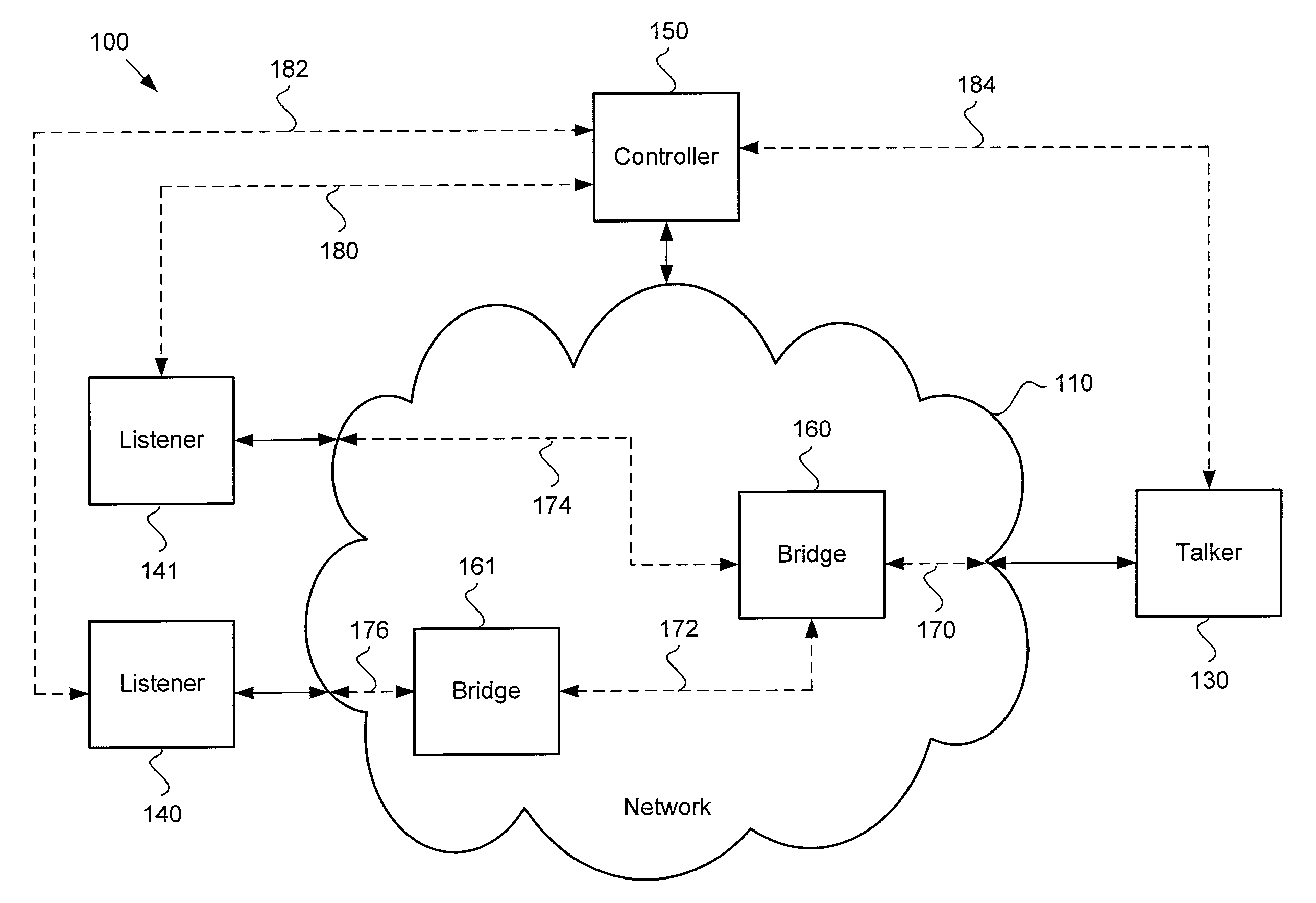
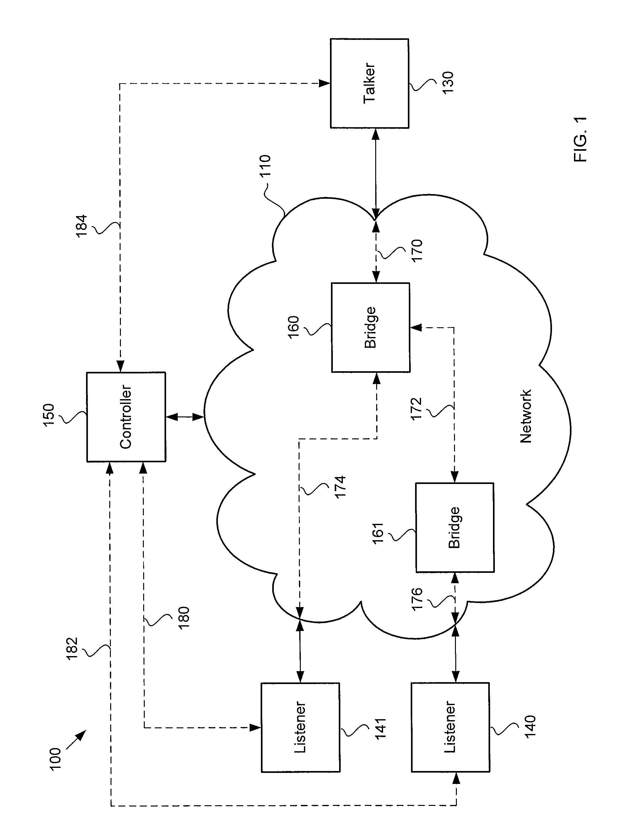
[0022]FIG. 1 illustrates an example network communication system 100 that may include a plurality of electronic devices, including electronic devices 130, 140, 141, and 150. More or fewer electronic devices may be included. One or more of t...


PUM


Abstract

A network communication system includes a talker that may communicate a data stream having an optimal presentation time to a plurality of listeners over a network, such as an Ethernet Audio/Video Bridging network. The optimal presentation time may be determined by a maximum latency among a plurality of latencies for connections between the talker and the listeners. A controller may communicate with the listeners to determine the maximum latency. The controller may also provide the maximum latency to the talker and the listeners. The talker may determine the optimal presentation time based on the maximum latency. The listeners may allocate an optimum amount of resources to buffer the data stream before the data in the data stream is presented.

Description

BACKGROUND OF THE INVENTION[0001]1. Technical Field[0002]This invention relates to an Ethernet Audio-Video Bridging (“AVB”) network, and more particularly to optimizing latency introduced in the AVB network.[0003]2. Related Art[0004]Audio / video (“A / V”) data may be transmitted in a network system from a source endpoint to a destination endpoint. To reach the destination endpoint, the data may pass through bridges located in the network. When a bridge receives the data, the bridge may determine a next location (e.g., a next bridge) to send the data. The time taken for the bridge to receive the data, determine where to send the data, and send the data to the next location is a time delay or a latency that increases the total time that elapses for the data to reach the destination endpoint.SUMMARY[0005]A network communication system may include a talker that is configured to transmit a data stream to a plurality of listeners configured to receive the data stream over a network, such as ...

Claims


Application Information

Patent Timeline
Patent Type & Authority Applications(United States)
IPC IPC(8): G06F15/173
CPCH04L12/1868H04N21/64738H04N21/242H04L12/1881H04L65/80H04L65/1069H04L65/1046
Inventor GELTER, AARONBOATRIGHT, ROBERTGUNTHER, CRAIG
Owner HARMAN INT IND INC
Why Eureka
Try Eureka