Automatic transfer switch having an interlock arrangement

a technology of interlocking arrangement and transfer switch, which is applied in the field of power management system, can solve the problems of power not being supplied to the panel bus from two sources at one time, the manual actuation transfer system may not be suitable in some cases, and the source cannot back-feed, so as to prevent the back-feeding of power

Active Publication Date: 2013-06-06
RELIANCE CONTROLS
View PDF4 Cites 1 Cited by
  • Summary
  • Abstract
  • Description
  • Claims
  • Application Information

AI Technical Summary

Benefits of technology

[0008]When primary power is restored, the auxiliary feeder switch is automatically and firstly switched from the ON position to the OFF position and then the primary feeder switch is automatically switched from the OFF position to the ON position. The interlinking between the feeder switches causes the switches to be switched in tandem thereby preventing the primary power supply from feeding power to the distribution circuits when the auxiliary power supply is feeding power to the distribution circuits.
[0018]It is another object of the invention to provide an electrical panel outfitted with a transfer switch that automatically connects the electrical panel to a auxiliary primary supply when primary power is interrupted and substantially simultaneously electrically isolates the electrical panel from the primary power supply to prevent the backfeeding of power when the primary power supply is restored.

Problems solved by technology

However, such a manually actuated transfer system may not be suitable in some cases, particularly when no one is in attendance or where more convenience is desired or required.
The result is that power cannot be supplied to a panel bus from two sources at one time, and one source cannot back-feed the other.
Heretofore, such interlock structures have been limited to manual transfer switches.

Method used


Image

  • Automatic transfer switch having an interlock arrangement
  • Automatic transfer switch having an interlock arrangement
  • Automatic transfer switch having an interlock arrangement

Examples


Embodiment Construction

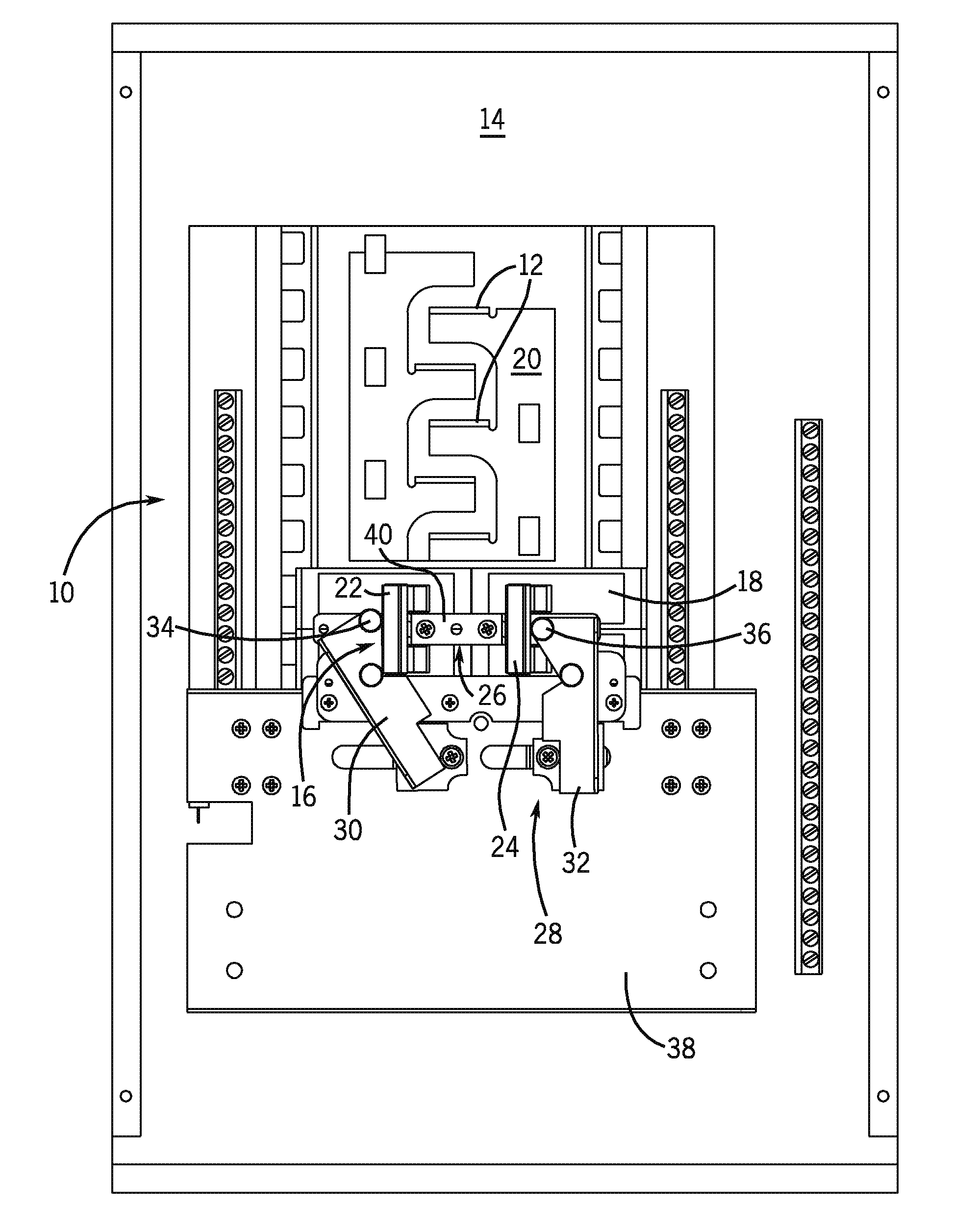
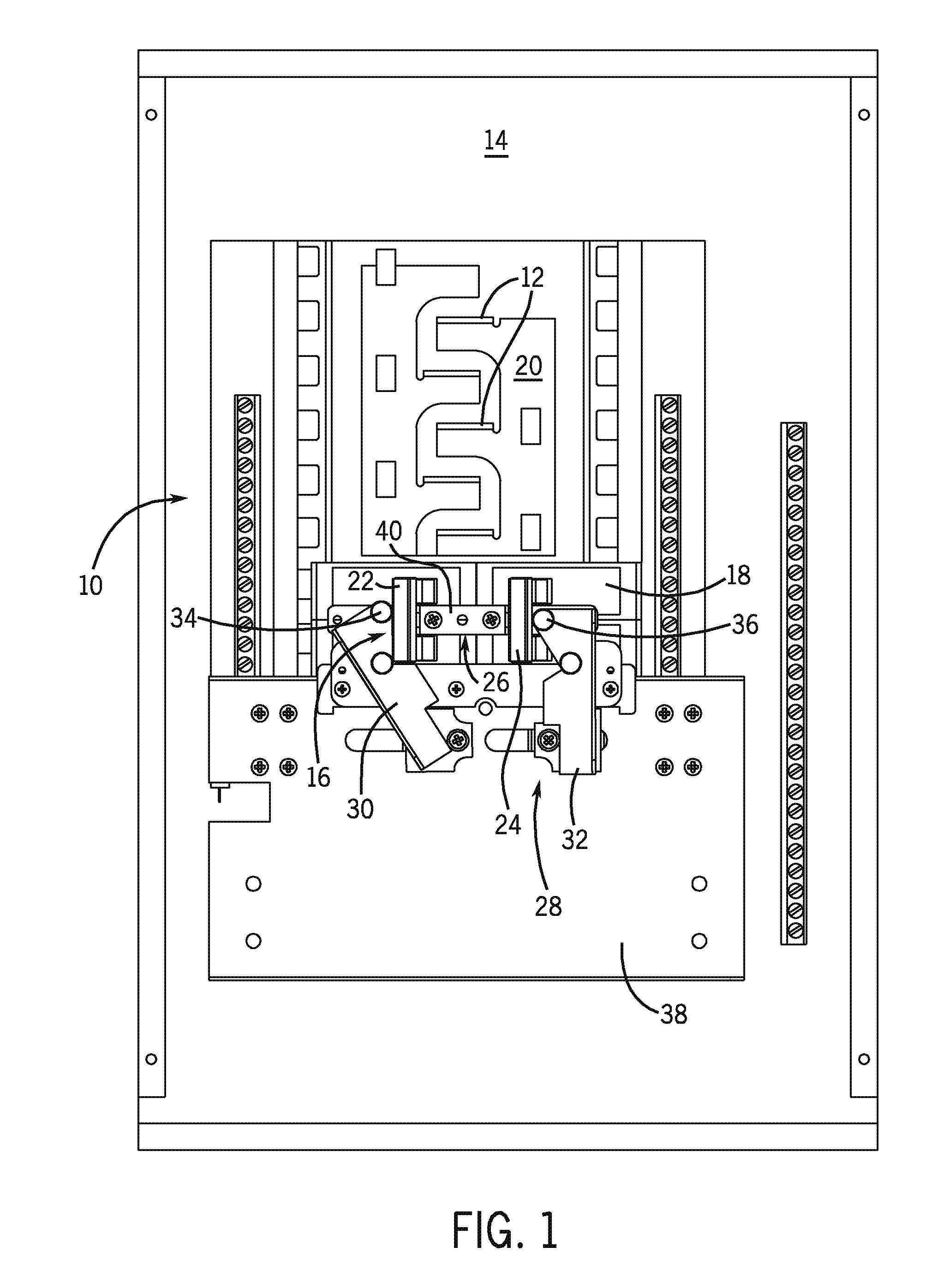
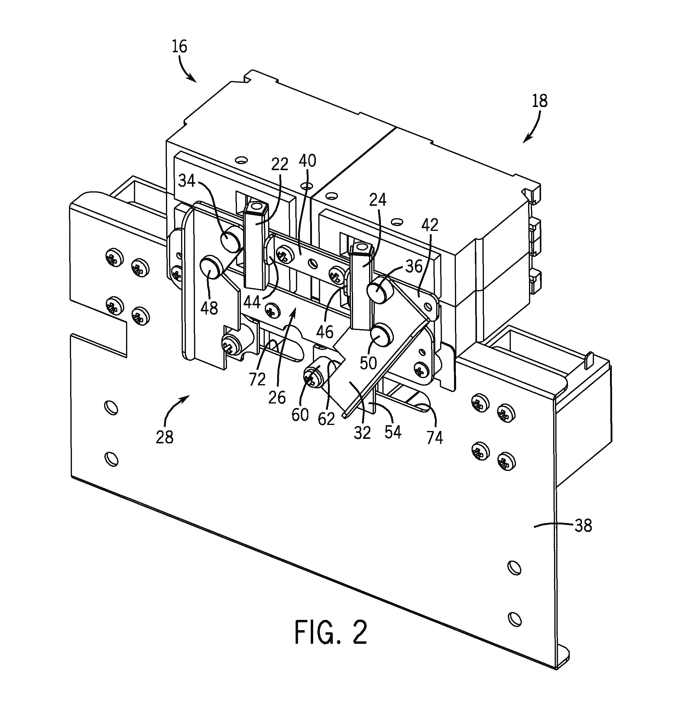
[0031]Referring now to FIG. 1, the present invention is particularly well suited for use with an electrical panel 10 having a series of circuit breakers (not shown) mounted on stabs 12, in a known manner, that control current flow to a number of distribution circuits. The electrical panel 10 is positioned within a cabinet 14 that is mounted or otherwise attached to a wall or similar support structure of a building. In addition to the distribution circuit breakers, the electrical panel 10 also includes a utility side power supply switch, which may be in the form of a breaker 16, and a generator side power supply switch, which may be in the form of a breaker 18. The power supply breakers 16, 18 control which power source energizes a bus bar 20.

[0032]Power supply breakers 16, 18 have respective switch handles 22, 24 that are interlinked by an interlock arrangement 26. The switch handles are movable between ON and OFF positions, wherein the ON position for a switch is defined by the swi...


PUM


Abstract

An automatic transfer switch to automatically electrically connect an electrical panel to a second power source, e.g., an electric generator, during interruption or failure of a first power source, e.g., a utility power supply, includes a powered interlock arrangement that is operative to prevent the electrical panel from being electrically connected to both power sources simultaneously.

Description

RELATED APPLICATIONS[0001]This is a continuation application of U.S. patent application Ser. No. 12 / 396,815, filed Mar. 3, 2009, which claims the benefit of U.S. Provisional Patent Application Ser. No. 61 / 033,810, filed Mar. 5, 2008, and entitled “Automatic Transfer Switch Having An Interlock Arrangement,” which is incorporated herein by reference.FIELD OF THE INVENTION[0002]The present invention relates generally to power management systems designed to energize the distribution circuits of an electrical panel using an auxiliary or backup power source during primary power interruption. More particularly, the invention is directed to an automatic transfer switch having interlinked switch members to prevent two power sources from feeding power to the electrical panel simultaneously.BACKGROUND OF THE INVENTION[0003]Manual transfer switches are sufficient for most applications where, during a utility power outage, a homeowner, landlord, or property manager is available to startup a gene...

Claims


Application Information

Patent Timeline
Patent Type & Authority Applications(United States)
IPC IPC(8): H02J3/00
CPCA61B5/02152A61B5/412A61M25/0026A61M2025/0002A61M2025/0037H02J9/00A61M2205/3331A61M2205/3344H02J3/005H02J7/00A61M2039/082
Inventor FLEGEL, DAVID D.
Owner RELIANCE CONTROLS
Why Eureka
Try Eureka