Method and device for target designation

a technology of target designation and target positioning, which is applied in the direction of satellite radio beaconing, cathode-ray tube indicators, mountings, etc., can solve the problem of restricting the wearer's ability to observe the terrain

Inactive Publication Date: 2013-06-06
BAE SYST BOFORS
View PDF4 Cites 11 Cited by
  • Summary
  • Abstract
  • Description
  • Claims
  • Application Information

AI Technical Summary

Benefits of technology

[0018]Most of the methods proposed above lend themselves particularly well to target-related designation where the principal purpose may be to make it easy for the wearer to have targets identified rapidly and easily and clearly visible in his field of vision. The designation can relate to other information, however, and according to one proposed method the designation is related to an area such as a surveillance area or the boundary area of a firing range. There may be a requirement, for example, to indicate the area in which a soldier has responsibility for observation or an area within which the soldier shall combat emerging threats. The designation can also be related to a navigation route that can be utilized to guide the user along a defined navigation route.
[0019]According to yet another further development of the method, it is proposed that the angle of the wearer's head relative to a designation should be indicated by means of points of light in two directions incorporated into the display worn by the wearer for the purpose of designation in the lateral sense and the vertical sense and in directions representing combinations of lateral and vertical directions. The introduction of a two-dimensional presentation enables the wearer to be given a more precise designation, for example in conjunction with target designation.
[0020]According to a proposed embodiment of the presentation device, it is suitable for the display to be arranged mounted on a helmet worn by the wearer. The helmet provides a stable structure on which to mount the at least three points of light included in the display.

Problems solved by technology

The systems concerned are complex systems which often also restrict the wearer's ability to observe the terrain.

Method used


Image

  • Method and device for target designation
  • Method and device for target designation
  • Method and device for target designation

Examples


Embodiment Construction

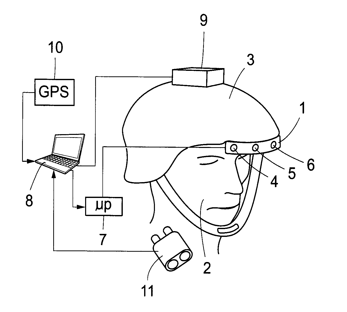
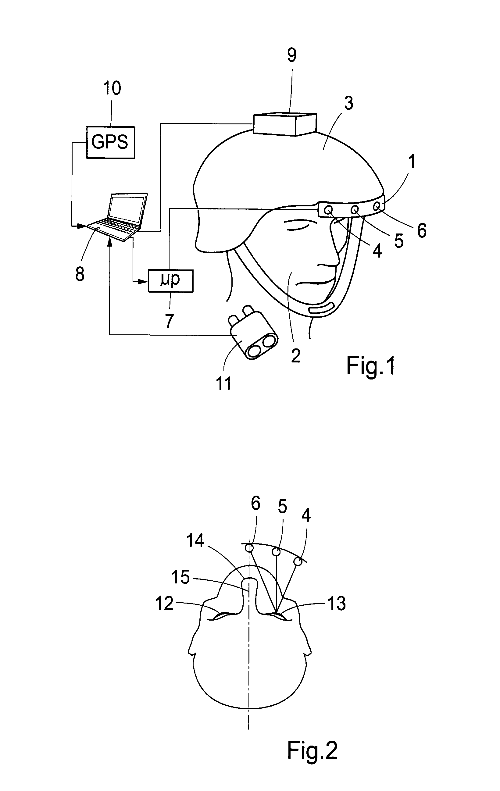
[0042]In the example of a presentation device illustrated in FIG. 1, a display 1 is mounted on a helmet 3 worn by a wearer 2. The display comprises light-emitting diodes which are preferably mounted adjacent to the edge of the helmet and, if desired, slightly below the edge 3.1 of the helmet with mutual spacing that may be in the order of 2.5 centimetres. The illustrated display comprises three light-emitting diodes (LEDs) 4, 5, 6, which form three separate points of light. The outer light-emitting diodes 4 and 6 are designed to emit light within a common colour spectrum, preferably red, while the light-emitting diode 5 in the middle is designed to emit light within a different colour spectrum, preferably green. The strength of the light-emitting diodes is dimensioned so that the brightness of the light-emitting diodes makes them visible out of doors in daylight, at the same time as the brightness can be adjusted to a low value for night time use; see the proposed method indicated b...


PUM


Abstract

The invention relates to a method and a presentation device for presenting information about the angle to a target to a wearer (2) by means of a display (1) worn by the wearer tracking movement of the wearer's head, the wearer's head movements being detected and the angle of the wearer's head relative to a target being indicated on the display. According to the invention, movements of the wearer's (2) head are detected independently of the target, the position of the wearer is determined locally, the position of the target is designated and the display is controlled on the basis of local information about the wearer's head movement, the wearer's position and the position designated as the target in order to indicate the angle of the wearer's head relative to the target.

Description

TECHNICAL FIELD[0001]The present invention relates to a method for presenting information about the angle to a target to a wearer by means of a display worn by the wearer tracking movement of the wearer's head, the wearer's head movements being detected and the angle of the wearer's head relative to a target being indicated on the display. The invention also relates to a presentation device for presenting information about the angle to a target to a wearer comprising a display worn by the wearer mounted in such a way as to track the wearer's head movements and a head tracker for detecting the wearer's head movements, which display indicates the angle of the wearer's head relative to the target and is controllable via a control unit.BACKGROUND[0002]Reference is made to U.S. Pat. No. 5,200,827 for examples of a previously disclosed display system worn by a wearer. The systems concerned are complex systems which often also restrict the wearer's ability to observe the terrain.[0003]Anot...

Claims


Application Information

Patent Timeline
Patent Type & Authority Applications(United States)
IPC IPC(8): G02B27/01
CPCG01S19/18G01S19/31G01S19/51G02B2027/014G02B27/0093G02B27/017G02B2027/0187G02B7/002
Inventor HORBERG, ULFANDERSSON, PETER
Owner BAE SYST BOFORS
Why Eureka
Try Eureka