High Pressure Fiber Optic Sensor System

a fiber optic sensor and high-pressure technology, applied in the field of fiber optic sensor systems, can solve problems such as compromising operation

Active Publication Date: 2013-06-13
THERMODYN
View PDF11 Cites 7 Cited by
  • Summary
  • Abstract
  • Description
  • Claims
  • Application Information

AI Technical Summary

Benefits of technology

[0006]The present application and the resultant patent thus provide a fiber optic sensor system. The fiber optic sensor system may include a small diameter bellows, a large diameter bellows, and a fiber optic pressure sensor...

Problems solved by technology

Although such fiber Bragg grating sensors are highly accurate, the harsh environmen...

Method used


Image

  • High Pressure Fiber Optic Sensor System
  • High Pressure Fiber Optic Sensor System
  • High Pressure Fiber Optic Sensor System

Examples


Embodiment Construction

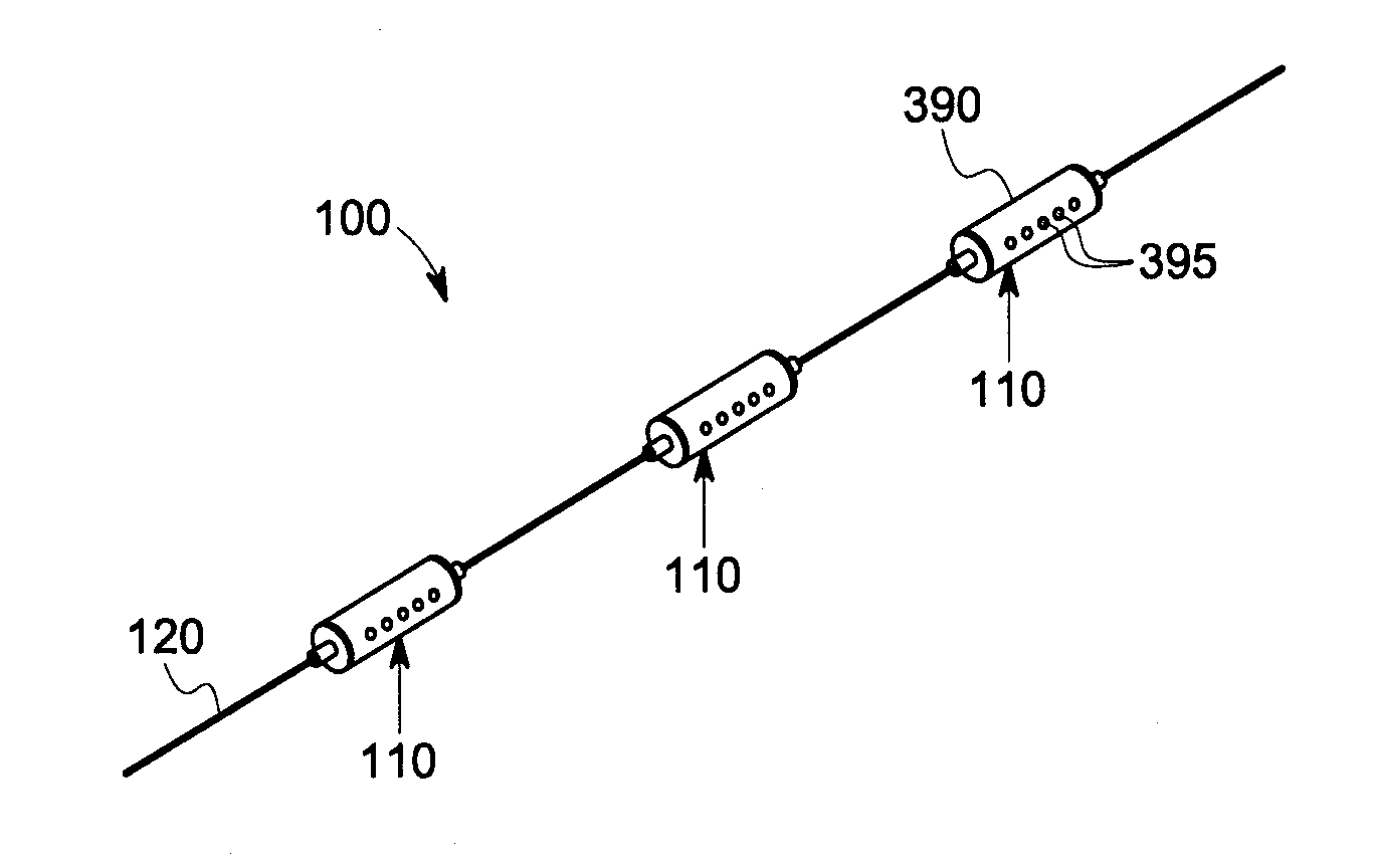
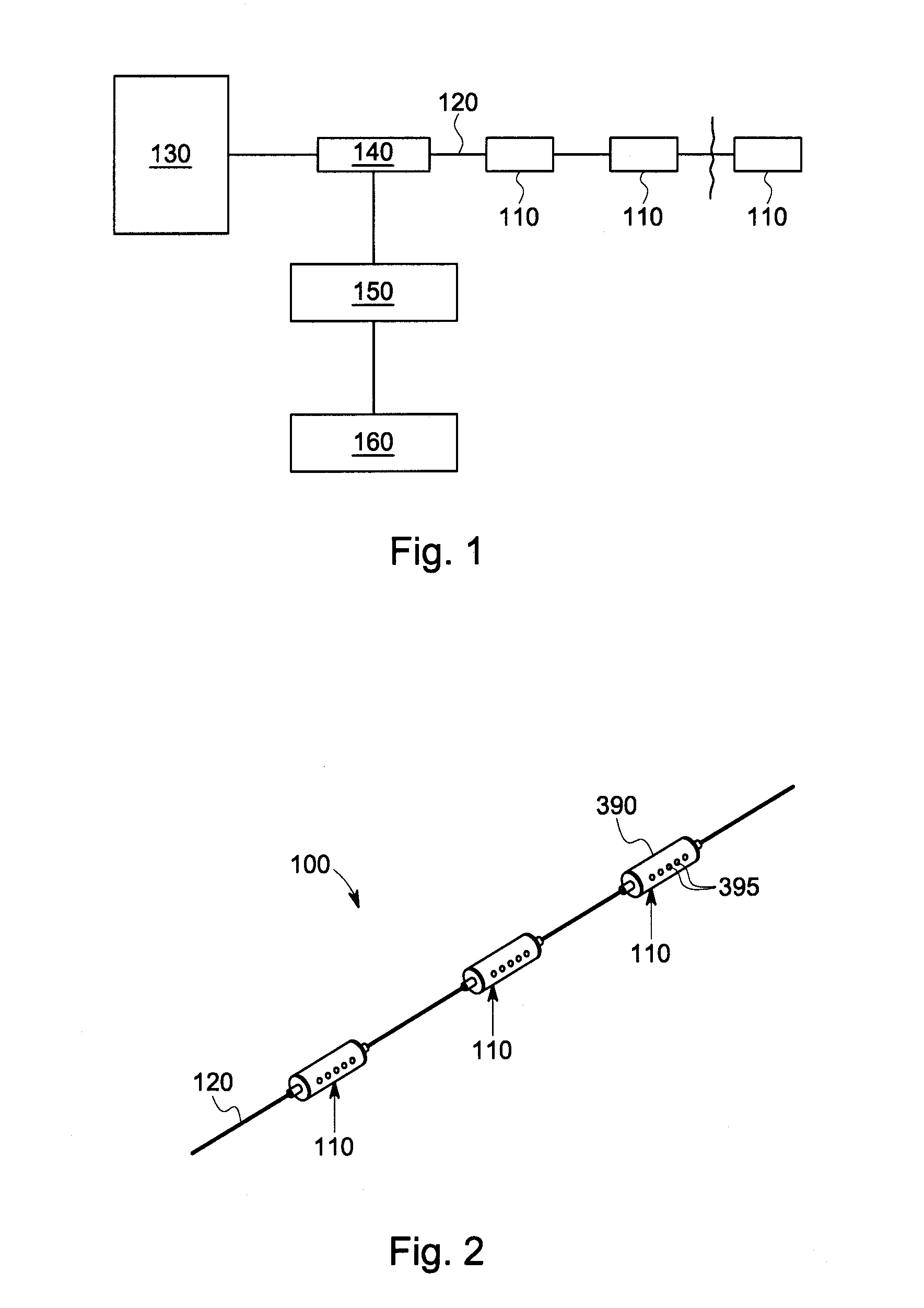
[0018]Referring now to the drawings, in which like numerals refer to like elements throughout the several views, FIG. 1 shows a schematic diagram of a fiber optic sensor system 100 as may be described herein. Generally described, the fiber optic sensor system 100 may include a number of sensors 110 attached to a fiber optic cable 120. Any number of sensors 110 may be used with a cable 120 of any length. As described above, the fiber optic sensor system 100 may be used in harsh environments such as geothermal, down hole, and the like. The sensors 110 may be connected in series to extend the range to be monitored.

[0019]The fiber optic sensor system 100 may include a light source 130. The light source 130 may be configured to illuminate the fiber optic cable 120 to facilitate the generation of reflected signals corresponding to a grating period of the cable 120. The fiber optic sensor system 100 also may include an optical coupler 140. The optical coupler 140 may manage incoming light ...


PUM


Abstract

The present application provides a fiber optic sensor system. The fiber optic sensor system may include a small diameter bellows, a large diameter bellows, and a fiber optic pressure sensor attached to the small diameter bellows. Contraction of the large diameter bellows under an applied pressure may cause the small diameter bellows to expand such that the fiber optic pressure sensor may measure the applied pressure.

Description

FEDERAL RESEARCH STATEMENT[0001]This invention was made with Government support under Contract No. DE-EE0002787, awarded by the U.S. Department of Energy (DOE). The Government has certain rights in this invention.TECHNICAL FIELD[0002]The present application and the resultant patent relate generally to fiber optic sensor systems and more particularly relate to a fiber optic sensor system for use in harsh environments such as geothermal and in the oil and gas industry for monitoring down hole parameters.BACKGROUND OF THE INVENTION[0003]Fiber Bragg gratings may be wavelength multiplexed along one fiber so as to be useful for measurements of strain and temperature. Specifically, the fiber Bragg gratings may be used as a pressure-temperature sensor by measuring the shift in Bragg wavelength caused by a change in hydrostatic pressure or a change in temperature. Fiber Bragg grating sensors thus may be used for multipoint temperature profile measurements because of low mass, low specific he...

Claims


Application Information

Patent Timeline
IPC IPC(8): G01L9/00
CPCE21B47/06G01L9/0039G01L27/002G01L19/0092G01L11/025
Inventor GUIDA, RENATOXIA, HUALEE, BOON K.DEKATE, SACHIN N.
Owner THERMODYN
Why Eureka
Try Eureka