Stent With Improved Flexibility and Method for Making Same

a technology of flexible stents and stents, applied in the field of flexible stents, can solve the problems of stent longitudinal rigidity, and high morbidity and mortality, and achieve the effect of improving longitudinal flexibility

Active Publication Date: 2013-06-13
MEDTRONIC VASCULAR INC
View PDF10 Cites 3 Cited by
  • Summary
  • Abstract
  • Description
  • Claims
  • Application Information

AI Technical Summary

Benefits of technology

[0014]One aspect of the present invention provides a stent having improved longitudinal flexibility and minimal apex to apex (i.e., peak to valley) interaction between adjacent rings.
[0016]Another aspect of the present invention provides a method for manufacturing a stent with improved longitudinal flexibility and increased apex to apex spacing between adjacent rings.

Problems solved by technology

One of the major complications associated with using stents has been thrombosis.
This complication is caused by clotting in the vicinity of the stent and is associated with high morbidity and mortality.
However, such conventional stents suffer from predilation stent longitudinal rigidity.
Accordingly, predilation longitudinal stent rigidity makes it much harder and oftentimes even impossible to thread the stent through long tortuous vessels and past constrictions and lesions.
Such attempts have included designs with decreased ring width, often referred to as decreased wire gauge, which resulted in increased longitudinal flexibility but decreased radial strength.
These conventional designs have resulted in inadequate stent apposition and / or inadequate vessel wall support.
This increases longitudinal flexibility but decreases the scaffolding affect of the stent.
The decreased scaffolding affect creates areas where the vessel wall is not adequately covered by the stent, which may lead to thrombosis and / or restenosis.
However, such conventional stents may suffer from abrasion or damage due to adjacent apexes (i.e., peaks and valleys) interacting during crimping and tracking, which may be caused by the close proximity of adjacent apexes coming into contact with one another due to links or weld not providing adequate clearance.
This interaction may cause abrasion or damage during the coating of the stent with a drug and / or polymer or during tracking of the stent through the anatomy.

Method used


Image

  • Stent With Improved Flexibility and Method for Making Same
  • Stent With Improved Flexibility and Method for Making Same
  • Stent With Improved Flexibility and Method for Making Same

Examples


Embodiment Construction

[0031]The foregoing and other features and advantages of the invention will be apparent from the following, more detailed description of the preferred embodiment of the invention, as illustrated with reference to the Figures. While specific embodiments are discussed in detail, it should be understood that this is done for illustrative purposes only. A person skilled in the art will recognize that other embodiments can be used without departing from the spirit and scope of the invention.

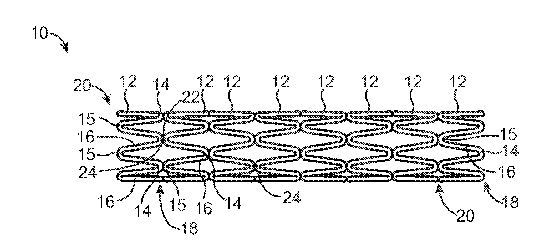
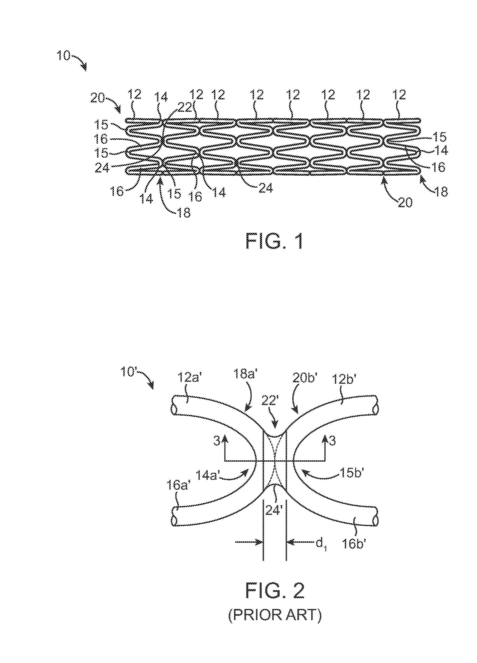
[0032]FIG. 1 illustrates a stent 10 according to an embodiment of the invention. As illustrated, the stent 10 includes a plurality of circumferential rings 12 that are each in the shape of a sinusoid. Each ring 12 includes a plurality of peaks 14 and a plurality of valleys 15 that are connected to each other by a plurality of segments 16. A proximal end 18 of the sinusoid has been arbitrarily labeled “peak” and a distal end 20 of the sinusoid has been arbitrarily labeled “valley.” It would be understo...


PUM

PropertyMeasurementUnit
Vickers hardnessaaaaaaaaaa

Abstract

A stent and a method for manufacturing a stent are provided. The stent includes a first ring having a plurality of peaks and a plurality of valleys, a second ring having a plurality of peaks and a plurality of valleys, and a connector that connects one of the peaks of the first ring to one of the valleys of the second ring. The connected peak of the first ring includes a deformed portion that extends towards the connected valley of the second ring. The method includes forming a first ring having a plurality of peaks and a plurality of valleys, forming a second ring having a plurality of peaks and a plurality of valleys, deforming a portion of at least one of the peaks of the first ring, and connecting the deformed portion of the peak of the first ring to one of the valleys of the second ring.

Description

RELATED APPLICATIONS[0001]This application is a Division of and claims the benefit of U.S. patent application Ser. No. 11 / 624,343 filed Jan. 18, 2007, now abandoned.BACKGROUND OF THE INVENTION[0002]1. Field of the Invention[0003]The present invention relates generally to a stent with improved flexibility. More specifically, the present invention relates to a welded stent having increased flexibility at the welded connections.[0004]2. Description of Related Art[0005]A stent is a prosthesis that is inserted into a body lumen and used, for example, for treating stenoses, strictures, and / or aneurysms therein. In the event of a stenosed vessel, a stent may be used to prop open the vessel after an angioplasty procedure. Once opened, the stent forms to the inner wall of the vessel, remains in place, and may help prevent restenosis. Additionally, in the event of an aneurysm or weakened vessel wall, stents may be used to provide support to, and reinforce the vessel wall.[0006]To perform such...

Claims


Application Information

Patent Timeline
Patent Type & Authority Applications(United States)
IPC IPC(8): B21F99/00A61F2/90
CPCA61F2/90A61F2250/0029C21D7/04Y10T29/49B21F99/00A61F2230/0054C21D2201/01
Inventor KRIVORUCHKO, MICHAELLESSAR, JOSEPH
Owner MEDTRONIC VASCULAR INC
Why Eureka
Try Eureka