Machined springs for injector applications

a technology of injection springs and machined springs, which is applied in the field of injection springs used to bias injection spring components, can solve the problems of loss of spring force, difficult assembly, and increase the number of parts, and achieve the effect of providing stiffness

Active Publication Date: 2015-06-30
COLLINS ENGINE NOZZLES INC
View PDF5 Cites 0 Cited by
  • Summary
  • Abstract
  • Description
  • Claims
  • Application Information

AI Technical Summary

Benefits of technology

[0007]In certain embodiments, the plurality of spring channels includes first and second helical spring channels. The helical spring channels wind in counter-rotational directions around the annular wall for uniform spring stiffness and reduced buckling of the spring body to one side under a substantially axial load.
[0010]In accordance with certain embodiments, the spring channels are circumferential spring channels, wherein each circumferential spring channel winds circumferentially around a portion of the annular wall to provide flexibility in the direction of the longitudinal axis and stiffness in a torque direction around the longitudinal axis circumferentially. There can be a plurality of pairs of the spring channels, each pair having an axially extending wall section separating the two channels at each channel end. The axially extending wall sections between channel ends of each axially adjacent pair of channels can be circumferentially offset from one another, by about 90° for example, for increasing uniformity in longitudinal flexibility of the annular wall. Each channel end can include an enlarged terminus for reducing stress concentrations.
[0014]In yet another embodiment, each machined spring channel is a circumferential spring channel as described above, wherein the first spring base is mounted to the inlet end of the injector body. The second spring base is mounted to a feed arm of the injector. A liquid conduit extends through the annular wall. The machined spring is configured and adapted to accommodate differential thermal expansion of the feed arm and liquid conduit and to provide stiffness to the inlet end of the injector body in torsion.

Problems solved by technology

Traditional springs in such applications can suffer from loss of spring force, can be difficult to assemble, add to part count, and take up considerable space.
For example, traditional wave springs used to bias valve components away from injector walls can loose their spring due to heat from welding operations on adjacent components.
The welding heat can anneal the spring and thereby render the spring ineffective.

Method used


Image

  • Machined springs for injector applications
  • Machined springs for injector applications
  • Machined springs for injector applications

Examples


Embodiment Construction

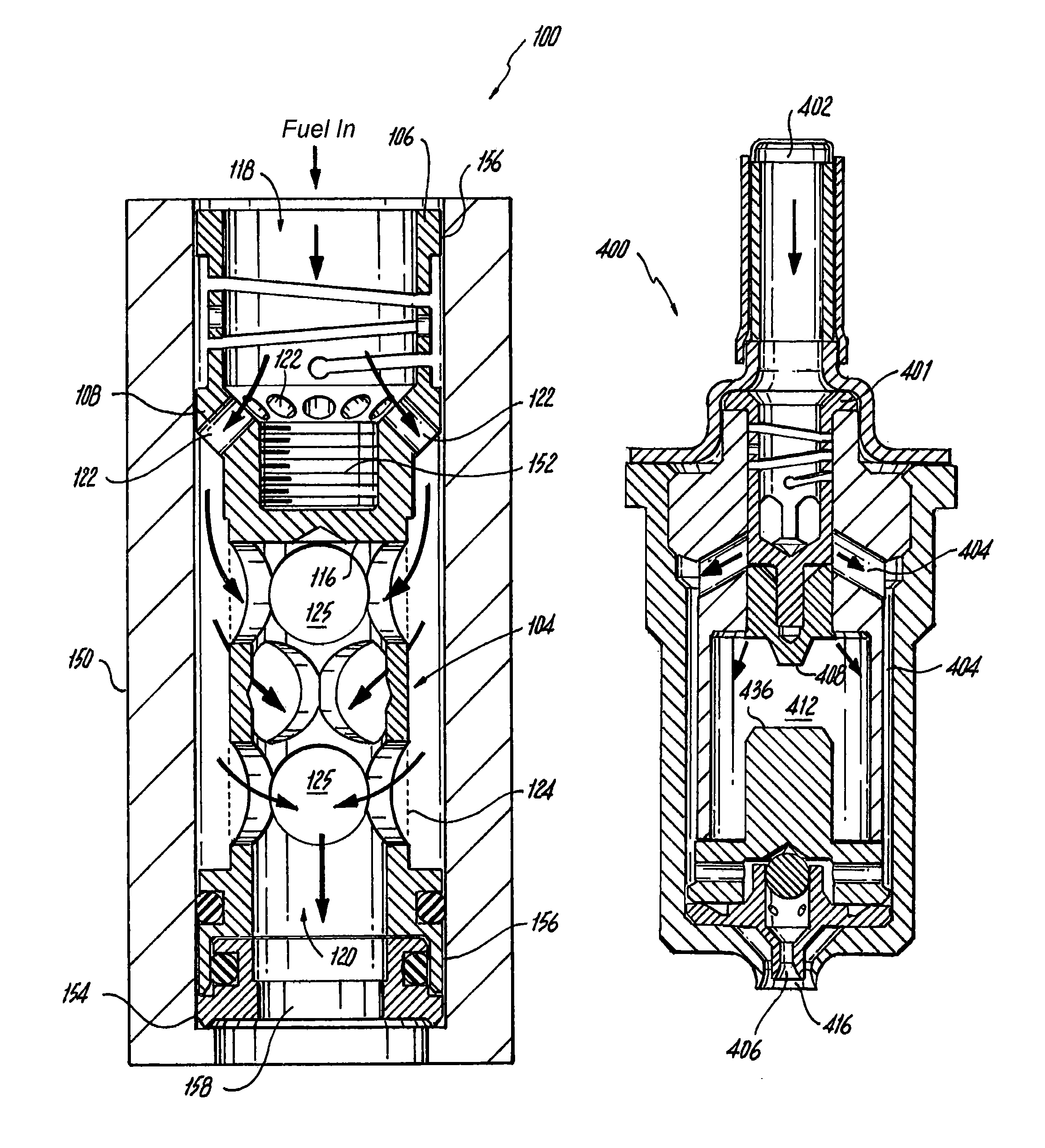
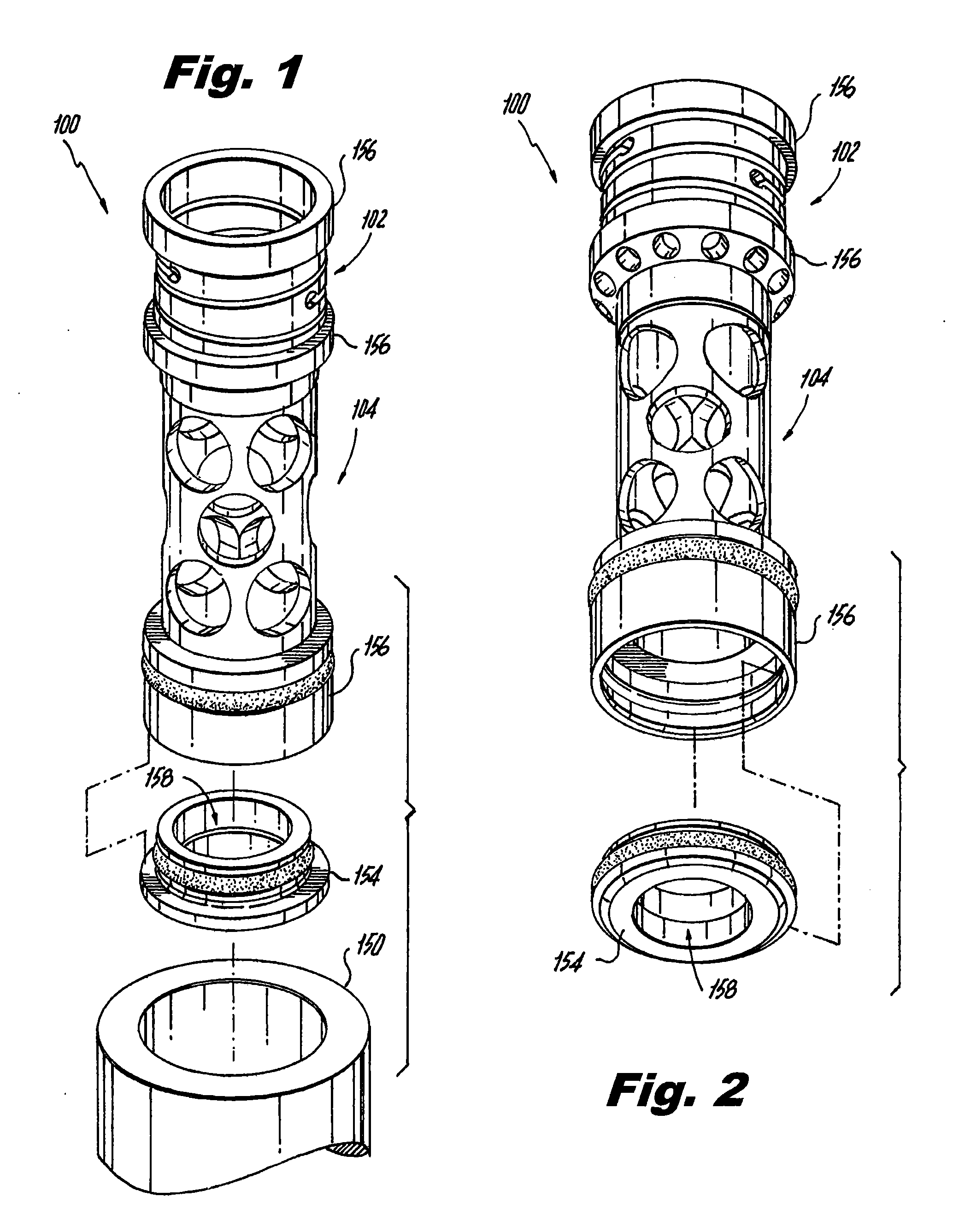
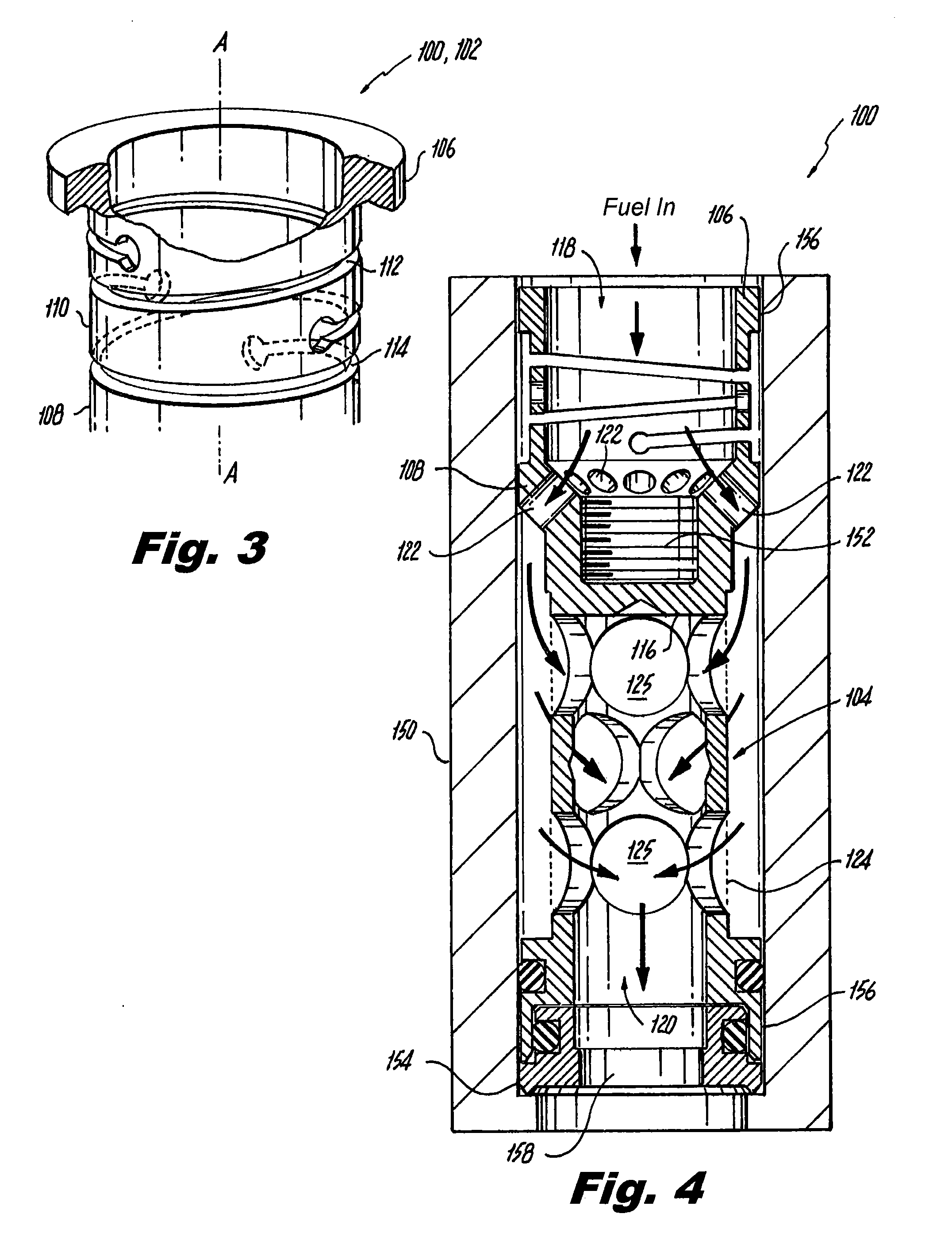
[0041]Reference will now be made to the drawings wherein like reference numerals identify similar structural features or aspects of the subject invention. For purposes of explanation and illustration, and not limitation, a partial view of an exemplary embodiment of a machined spring in accordance with the invention is shown in FIG. 1 and is designated generally by reference character 100. Other embodiments of machined springs in accordance with the invention, or aspects thereof, are provided in FIGS. 2-24, as will be described. The systems and methods of the invention can be used to improve spring performance, reduce part count, reduce part size, and to simplify assembly and manufacture, for example in fuel injectors for gas turbine engines.

[0042]Machined spring 100 includes a spring portion 102 and a liquid strainer 104 integral with spring portion 102. FIGS. 1 and 2 show the spring portion 102 and integral liquid strainer 104 from upstream and downstream perspectives, respectively...


PUM

PropertyMeasurementUnit
stiffnessaaaaaaaaaa
flexibilityaaaaaaaaaa
stress concentrationsaaaaaaaaaa

Abstract

A machined spring for injector applications includes opposed first and second spring bases separated apart along a longitudinal axis. A spring body connects the first and second spring bases. The spring body includes a generally annular wall with a plurality of spring channels defined therethrough, such as machined channels. Exemplary applications for such machined springs include liquid strainers, valve components, and structural components for accommodating thermal expansion in injectors.

Description

BACKGROUND OF THE INVENTION[0001]1. Field of the Invention[0002]The present invention relates to injectors, and more particularly to springs used to bias injector components.[0003]2. Description of Related Art[0004]Traditional springs are used in a variety of applications in injectors and nozzles, such as fuel injectors for gas turbine engines. Exemplary uses of springs in conventional injectors include use in biasing fuel strainers into position, biasing valve hold down components away from external injector walls, biasing scheduling valve components, and the like. Traditional springs in such applications can suffer from loss of spring force, can be difficult to assemble, add to part count, and take up considerable space. For example, traditional wave springs used to bias valve components away from injector walls can loose their spring due to heat from welding operations on adjacent components. The welding heat can anneal the spring and thereby render the spring ineffective.[0005]S...

Claims


Application Information

Patent Timeline
Patent Type & Authority Patents(United States)
IPC IPC(8): F02M59/00F16F1/04F16F1/02B01D29/11F02C9/28F02C7/232F02M61/20F02M61/18B05B1/14B05B15/00
CPCF02C7/232F02M61/20F02M61/18B05B1/14B05B15/008F16F1/042F16F1/02B01D29/111F02C9/285F05D2260/38F05D2260/52B05B15/40F23K5/14F23K5/18F23R3/28F23K2300/202Y10T137/794
Inventor PFEFFER, BRETT A.CAPLES, MARK A.
Owner COLLINS ENGINE NOZZLES INC
Why Eureka
Try Eureka