Spring suspension for a handlebar-steered vehicle

a technology of spring suspension and handlebar, which is applied in the direction of shock absorbers, cycle springs, steering devices, etc., can solve the problems of adding extra weight to the suspension system, and achieve the effect of reducing the weight of the suspension

Active Publication Date: 2013-07-30
SRAM CORPORATION
View PDF28 Cites 5 Cited by
  • Summary
  • Abstract
  • Description
  • Claims
  • Application Information

AI Technical Summary

Benefits of technology

[0003]The present invention provides a coil spring suspension including a coil spring extending beyond a first tube which allows the use a short tube thereby reducing the weight of the suspension. The coil spring suspension may be used on a handlebar-steered vehicle such as a bicycle or motorcycle. A first end of the coil spring is disposed within the first tube and is fixedly supported proximate a first end of the first tube. The coil spring extends beyond the second end of the first tube. A shaft fixedly supports the second end of the coil spring. The shaft and the first tube slidably displaced relative to each other upon suspension loading to lengthwise compress the coil spring. A guide is disposed within the first tube and connected to the coil spring between first and second ends of the coil spring. The guide is displaced within the first tube and is connected to the coil spring between the first and second ends of the coil spring. The guide is displaced within the coil spring to limit lateral displacement of the coil spring and thereby shield the coil spring from contact with the first tube.
[0004]In one embodiment of the present invention, the guide includes an opening slidably receiving and guiding the shaft within the first tube. The guide is non-elastomeric. A smaller diameter segment of the coil spring extends lengthwise between the guide and the second end of the coil spring. The guide has an outer diameter greater than the larger diameter segment of the coil spring. A larger diameter segment of the coil spring has an outer diameter that substantially equals an inner diameter of the first tube, reducing buckling of the coil spring. The coil spring is helically connected to the guide. A first end of the shaft has a cap with a greater diameter than the opening of the guide. A second end of the shaft fixedly supports the second end of the coil spring.

Problems solved by technology

A disadvantage of this spring stack-up is a longer upper tube, thus adding extra weight to the suspension system.

Method used


Image

  • Spring suspension for a handlebar-steered vehicle
  • Spring suspension for a handlebar-steered vehicle
  • Spring suspension for a handlebar-steered vehicle

Examples


Embodiment Construction

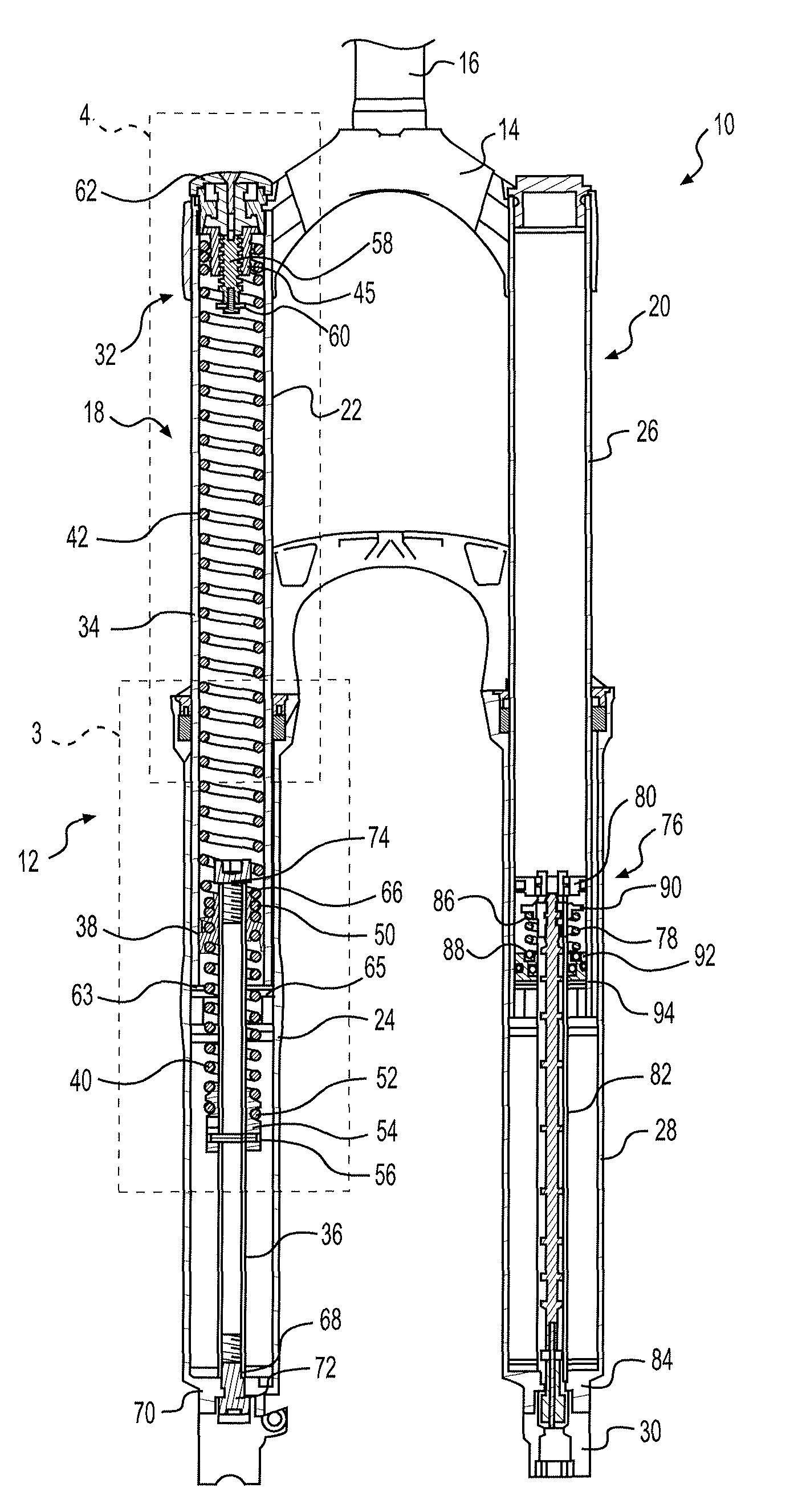
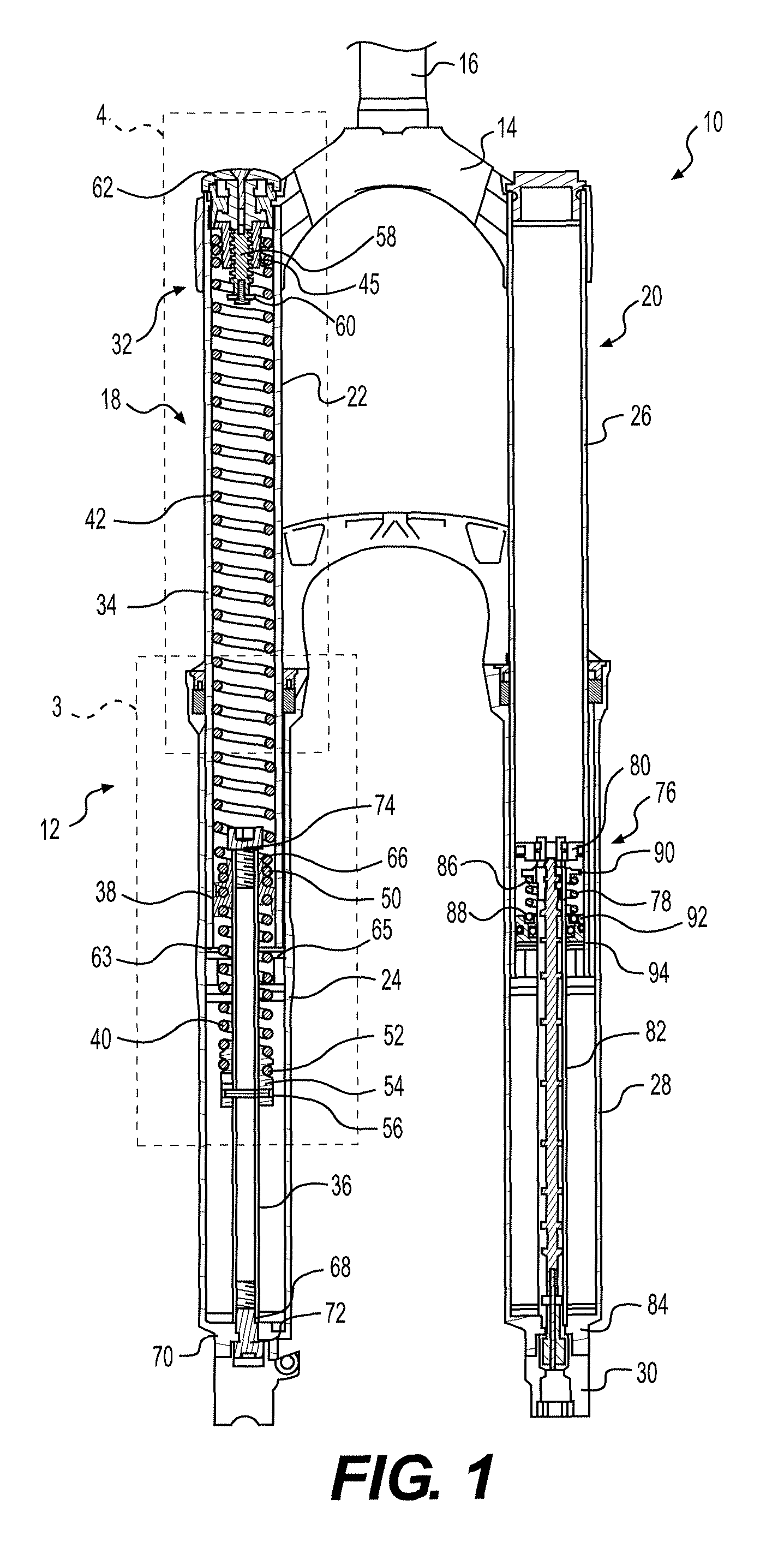
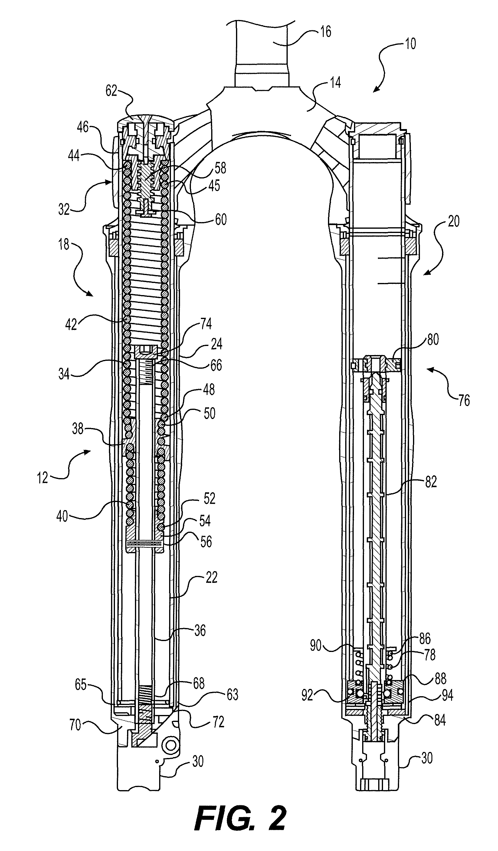
[0014]FIGS. 1-4 illustrate a bicycle front suspension fork 10 that includes a coil spring suspension 12 according to one embodiment of the present invention. The fork 10 includes a crown 14 connected to a steerer tube 16 and first and second legs 18, 20. The first leg 18 includes a first tube 22 (in this embodiment, an inner upper tube) slidably disposed within a second tube 24 (in this embodiment, an outer lower tube). The second leg 20 includes a third tube 26 (in this embodiment, an inner upper tube) slidably disposed within the fourth tube 28 (in this embodiment, an outer lower tube). The first and third tubes 22, 26 are connected to the crown 14 and the second and fourth tubes are connected to a wheel axle (not shown) through dropouts 30. It is to be understood that although the present invention is described with respect to a front suspension fork, the suspension system may also be embodied in a rear shock, a seat post, or at other locations on a bicycle frame. Further, the su...


PUM


Abstract

A coil spring suspension designed for a handlebar-steered vehicle. The coil spring suspension generally includes a first tube, a coil spring, a shaft and a guide. A first end of the coil spring is disposed within the first tube and fixedly supported proximate a first end of the first tube. The coil spring extends beyond a second end of the first tube. The shaft fixedly supports a second end of the coil spring. The shaft and the first tube are slidably displaced relative to each other upon suspension loading to lengthwise compress the coil spring. The guide is disposed within the first tube and connected to the coil spring between the first and second ends of the coil spring. The guide is displaced with the coil spring under suspension loading and limiting lateral displacement of the coil spring.

Description

BACKGROUND OF INVENTION[0001]The present invention relates to suspension systems, and more particularly, to a spring suspension that includes a spring extending lengthwise beyond a suspension tube housing the spring and a guide disposed within the suspension tube to limit lateral displacement of the spring.[0002]Spring suspension systems, typically coil spring suspensions used on handlebar-steered vehicles such as bicycles and motorcycles, include an upper tube slidable within a lower tube and a coil spring assembly disposed entirely within the upper tube. The coil spring assembly may include positive and negative coil springs stacked in series. To obtain the desired riding characteristics, the coil springs are assembled to have some preload, typically requiring the springs be trapped inside the upper tube. A disadvantage of this spring stack-up is a longer upper tube, thus adding extra weight to the suspension system. Accordingly, there is a need for a suspension system that uses a...

Claims


Application Information

Patent Timeline
Patent Type & Authority Patents(United States)
IPC IPC(8): F16F9/48
CPCB62K25/08F16F1/128B62K2025/048B62K2201/04
Inventor POWELL, ROBERT
Owner SRAM CORPORATION
Why Eureka
Try Eureka