Concrete-filled steel tube beam column connecting joint capable of being replaced after earthquake

A technology for connecting concrete-filled steel tubes and beams and columns, which is applied in the fields of earthquake resistance, building types, and buildings. It can solve problems such as the difficulty of installing concrete-filled steel tube beams and columns, and the impossibility of rapid repair of concrete-filled steel tube structures, achieving stable support, convenient assembly, and integrity sexual effect

Active Publication Date: 2021-08-31
CHONGQING UNIV
View PDF21 Cites 4 Cited by
  • Summary
  • Abstract
  • Description
  • Claims
  • Application Information

AI Technical Summary

Problems solved by technology

[0004] Aiming at the deficiencies of the prior art, the present invention provides a replaceable concrete-filled steel tube beam-column connection node after an earthquake, which has the advantage of more convenient installation of the concrete-filled steel tube beam-column in the later stage, and solves the problem that the existing concrete-filled steel tube structure cannot be quickly repaired after the earthquake. Difficulty in installing steel pipe concrete beams and columns in the later stage

Method used


Image

  • Concrete-filled steel tube beam column connecting joint capable of being replaced after earthquake
  • Concrete-filled steel tube beam column connecting joint capable of being replaced after earthquake
  • Concrete-filled steel tube beam column connecting joint capable of being replaced after earthquake

Examples


Embodiment 1

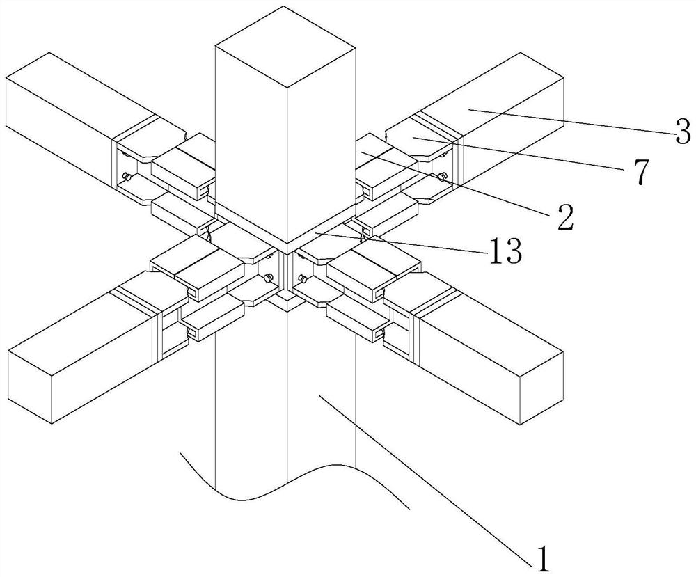
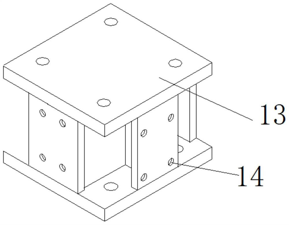
[0040] Such as Figure 1~4 A post-earthquake replaceable CFST beam-to-column joint is shown, including CFST columns 1. There are two CFST columns 1, namely the upper CFST column and the lower CFST column, and the upper CFST column and the lower CFST column. A prefabricated node frame 13 is arranged between the steel tube concrete columns. The prefabricated node frame 13 includes a cross-shaped steel member and six steel plates 5 welded on the upper and lower sides of the cross-shaped steel member and in the surrounding direction. The threaded holes 14 are provided at the four corners of the steel plate 5. A steel plate 5 is pre-embedded at the end of the steel tube concrete column and the lower steel tube concrete column opposite to the prefabricated node frame 13, and the four corners of the steel plate 5 are welded with threaded sleeves 15. The upper concrete-filled steel tube column and the lower steel tube concrete column are fixedly connected to the steel plates with thre...

Embodiment 2

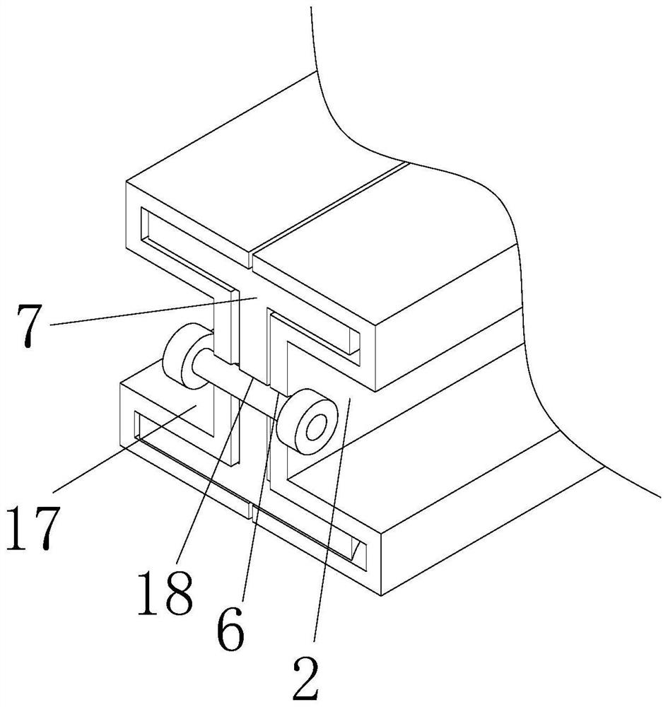
[0048] Such as figure 1 , 3 ~8 shows a post-earthquake replaceable steel pipe concrete beam-column connection node. The difference between Embodiment 2 and Embodiment 1 is that the bow-shaped connector 1 2 and the bow-shaped connector 2 17 are assembled on the bow-shaped connector 1 2 and the bow-shaped The steel beam 7 in the connector two 17 is fixed by fasteners, that is, the front side of the arc connector one 2 and the arc connector two 17 vertical plates are all provided with a draw-in groove 25, and the front and rear sides of the steel beam 7 vertical plates Both sides are fixedly connected with the support bar 11 that is slidingly connected to the inside of the card slot 25. The insides of the two support bars 11 are provided with the same structure. The inside of the support rod 11 extends to the outside of the support rod 11, and the inside of the support rod 11 is provided with a fixed support device.

[0049] The fixed supporting device comprises a power rod 10,...

Embodiment 3

[0054] Such as Figure 9 A post-earthquake replaceable concrete-filled steel tube beam-column connection node is shown. The difference between Embodiment 3 and Embodiment 1 is that the bow-shaped connector 1 2 and the bow-shaped connector 2 17 can also be assembled on the steel beam in a tooth-like splicing manner. 7, that is, the splicing parts of bow-shaped connector one 2 and bow-shaped connector two 17 are interspersed with thin steel bars 16 along the length direction, and the ends of thin steel bars 16 are welded to the joints of bow-shaped connector one 2 and bow-shaped connector two 17 to realize the bow-shaped connection The positions of the first piece 2 and the second bow-shaped connector 17 are fixed, and the first bow-shaped connector 2 and the second bow-shaped connector 17 are fixed on the steel beam 7 . In addition, the tooth shape can be square teeth, rectangular teeth or equilateral triangular teeth.


PUM


Abstract

The invention relates to a concrete-filled steel tube beam column connecting joint capable of being replaced after an earthquake. The concrete-filled steel tube beam column connecting joint comprises a prefabricated joint frame with threaded holes formed in the upper side, the lower side and the peripheral end face, the upper side and the lower side of the prefabricated joint frame are connected with an upper steel tube concrete column and a lower steel tube concrete column through bolts, the periphery of the prefabricated joint frame is connected with steel beams through bolts, the vertical section of the steel beams is I-shaped, arc-shaped stress grooves are formed in the front side and the rear side of a steel beam flange plate, the end, away from the prefabricated joint frame, of the steel beam is connected with a steel tube concrete beam through bolts, the surface of the steel beam is slidably connected with a first arch-shaped connecting piece and a second arch-shaped connecting piece which are spliced with each other, the first arch-shaped connecting piece, the second arch-shaped connecting piece and the steel beam are fixedly connected through fasteners, the dog-bone type steel beam can be prevented from buckling through the arch-shaped connecting pieces, the strength of the steel beam is enhanced to a certain degree, the energy dissipation capacity is enhanced, the ductility is improved, meanwhile, the steel beam is protected to a certain degree, and the service life of the steel beam is prolonged to a certain degree.

Description

technical field [0001] The invention belongs to the technical field of prefabricated concrete buildings, in particular to a replaceable steel pipe concrete beam-column connection node after an earthquake. Background technique [0002] The prefabricated concrete structure has been vigorously promoted in my country in recent years due to its advantages of energy saving, environmental protection, time saving and high efficiency, and convenient construction. As the core part of the prefabricated concrete structure, concrete beam-column joints and their connection methods have always been popular in the academic and engineering circles. Important topics of research focus. [0003] At present, in some traditional prefabricated concrete structures, the beams and columns can be prefabricated, and the joints are mainly connected by cast-in-place, in order to achieve the purpose of "equivalent to cast-in-place" for the whole structure; but the cast-in-place method can certainly ensure ...

Claims


Application Information

Patent Timeline
Patent Type & Authority Applications(China)
IPC IPC(8): E04H9/02E04B1/98
CPCE04H9/021E04B1/98
Inventor 白久林谢彬陈辉明杨经纬欧进萍金双双胡少伟
Owner CHONGQING UNIV
Why Eureka
Try Eureka