Bedding box for use with compact excavator

a compact excavating and box body technology, applied in the field of box body, can solve the problem that the lifting of the box from one end is often not sufficiently secure for transportation, and achieve the effect of convenient transportation

Inactive Publication Date: 2014-07-29
REUTHE JAMES T
View PDF8 Cites 3 Cited by
  • Summary
  • Abstract
  • Description
  • Claims
  • Application Information

AI Technical Summary

Benefits of technology

[0006]The present invention is for a bedding box for storing bedding stone and similar materials at a construction site, and which is particularly useful for regions of the site where access is limited. The bedding box is configured to be useful for smaller, compact excavators of the type having a scraper blade, and is further configured so as to be readily transported by the excavator for substantial distances over highly irregular surfaces.
[0008]Wing plates are attached to the side plates at the container upper rim and are canted with respect to the same by an angle ω to extend upward and outward from the container. Having the wing plates so placed provides two functions. The first function is to allow wider loading buckets to dump material into the bedding box without spillage; the wing plates similarly serve to help retain material in the box when pushed by scooping action of an excavator bucket removing material from the box. The second function is that, by having the wing plates canted, they form angle members with the side plates to increase the rigidity of the container and reduce buckling. Gussets are attached to the side plates and to the wing plates; these gussets not only increase the rigidity of the wing plates, but also serve to further stiffen the sidewalls.
[0010]A proximal end frame is affixed to the proximal end plate of the container and is configured so as to reinforce the proximal end plate. In addition to supplying reinforcement of the proximal end plate of the container, the proximal end frame also allows attachment of one or more support brackets configured to be engagable with a scraper blade of the excavator. The support bracket(s) provide a downward-facing bearing surface that can rest atop the scraper blade to be supported thereon, thereby providing support for the bedding box in combination with support by the excavator bucket engaging the distal end frame when the bedding box is to be transported by the excavator. When the bedding box is supported at both ends in such manner, it can be securely transported by the excavator moving from one location to another without risk of being dislodged by the movement of the excavator.
[0011]The bedding box is also provided with at least two skids residing below the bottom plate and substantially spanning the distance between the proximal end plate and the distal end plate. These skids serve two functions; first, they allow easier movement over the terrain on which the bedding box resides, and second, they enhance the rigidity of the bottom plate thereby further strengthening the bedding box. The height and spacing of the skids can be set to accommodate the tines of a forklift, allowing the bedding box to be lifted if the weight distribution is set so as to allow the box to balance on the forklift tines. The mass of the distal end frame is sufficiently large that the bedding box can be readily configured to allow it to be lifted by a forklift positioned at the distal end.
[0012]In some embodiments, wear bars reside in the container and attach to the proximal and distal ends and to the bottom plate. These wear bars prevent damage to the bottom and end plates of the container, as well as to provide strengthening of the bottom plate against the forces resulting from loading the box.
[0013]It is preferred for an angle δ to be maintained between the distal end frame (and the distal end plate to which it is affixed) and a line normal to the bottom plate, and similarly for the proximal end plate to be inclined by an angle π. These angles allow material loaded into the container to flow to the bottom while providing a greater area into which material can be dumped from a loader scoop or similar implement, without increasing the length of the bottom plate. The angle of the distal end frame may also simplify the insertion of the excavator bucket between the lift bar and the lower reinforcing bar.

Problems solved by technology

This allows the box to be lifted from one end by an excavator bucket in a manner similar to that of a large conventional bedding box, allowing the excavator to reposition the box at the site while the excavator remains stationary; however, due to the relatively small size and weight of the box, lifting it from one end is frequently not sufficiently secure for transport when the excavator itself is moved from one location to another.

Method used


Image

  • Bedding box for use with compact excavator
  • Bedding box for use with compact excavator
  • Bedding box for use with compact excavator

Examples


example

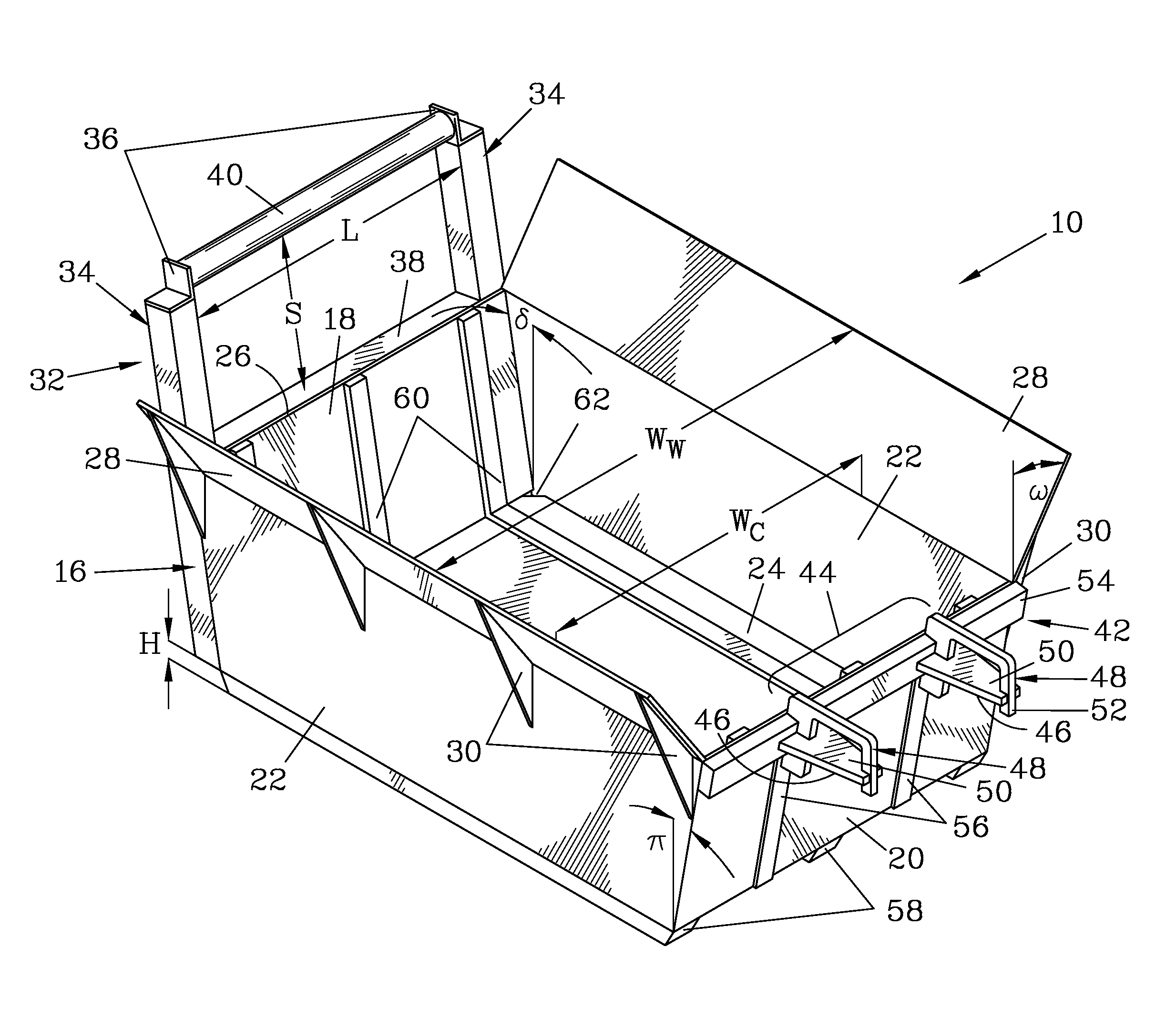
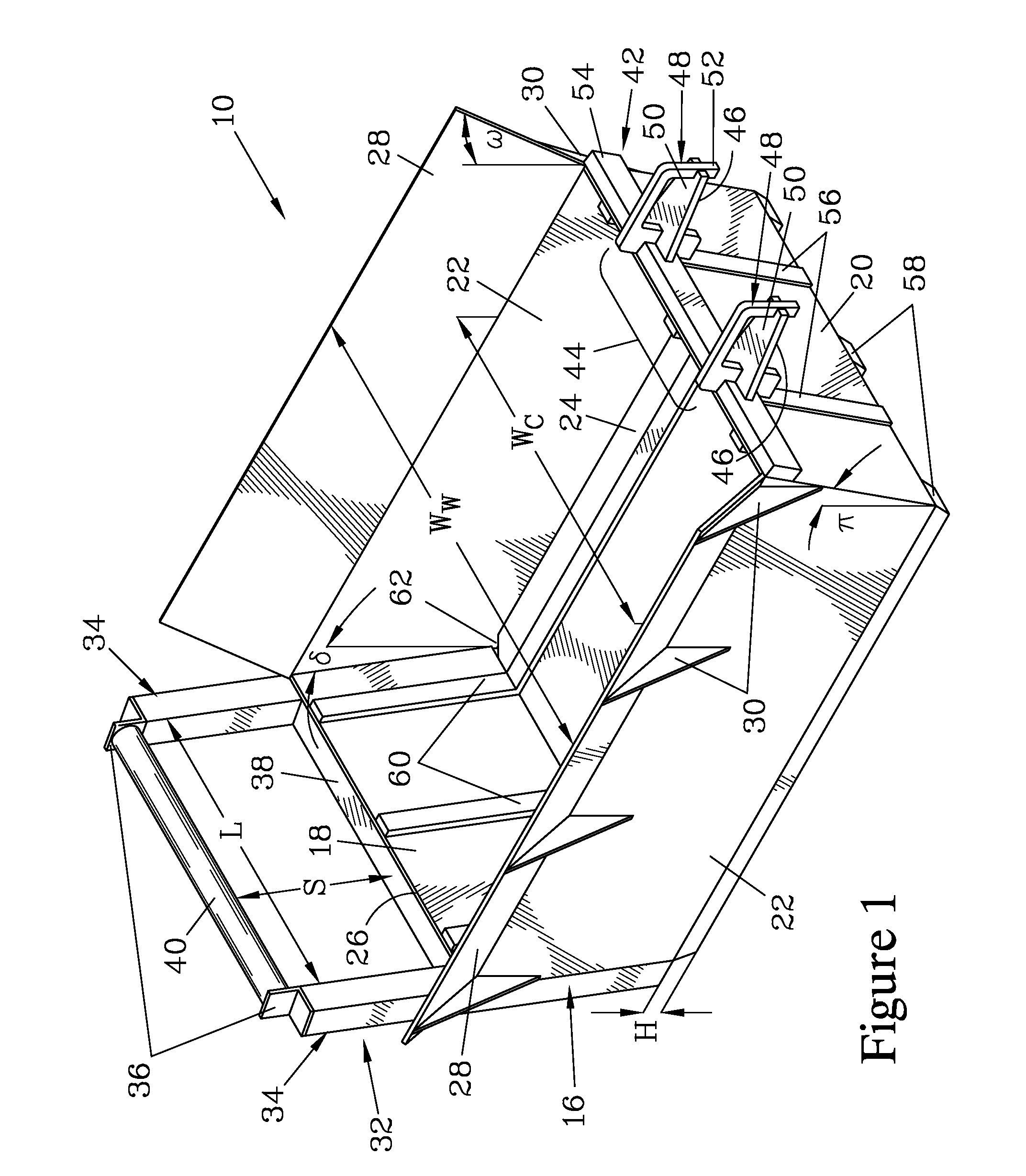
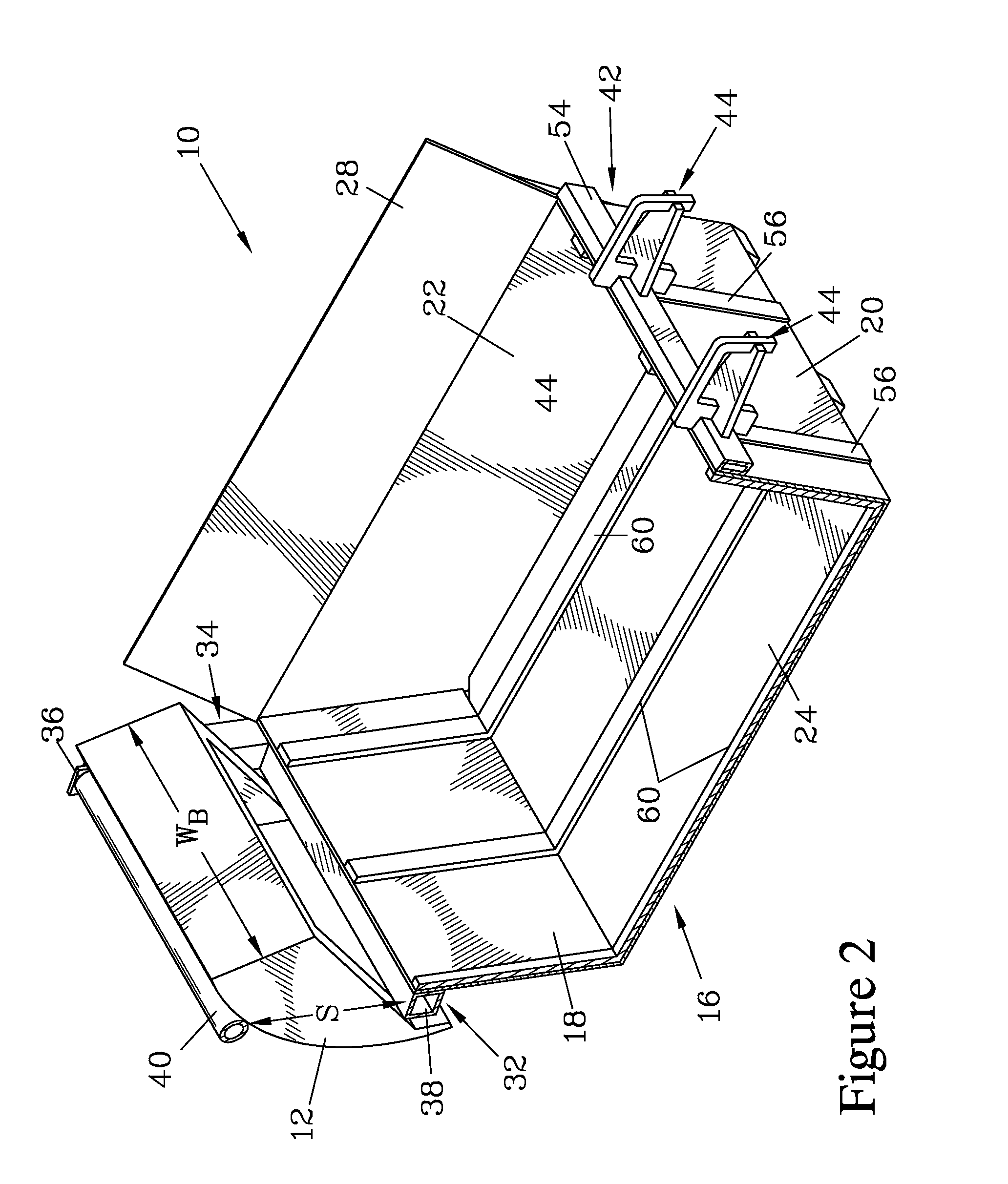
[0049]A bedding box having a configuration similar to the embodiments shown in FIGS. 1-4 was constructed for use with a 12,000 lb. excavator. The end, side, bottom, and wing plates were fabricated from 10 gauge steel to create a container with a container width WC of about 4′8″ and a length at the bottom of 6′5″. The end plates were sloped at about 25°, and the container had a height of about 2′, resulting in a length at the container rim of about 7′6″. The wing plates were 1′ wide, and angled at 45° to provide a wing maximum width WW of about 6′. The wing plates were supported by gussets also formed from 10 gauge stock. Wear bars of 3″×¼″ bar stock were added inside the container.

[0050]The distal end frame was constructed of 3″ square tubular stock, with the lift bar formed of 3″ round tube. The separation S between the lift bar and the reinforcing bar was 20½″. While this separation was found to be satisfactory for the 12,000 lb. excavator, it was found to be too large for the buc...


PUM


Abstract

A bedding box has a container formed by sloped end plates and side plates joined to a bottom plate, with gusseted wing plates reinforcing the side plates. The wing plates extend outwards from the container to facilitate loading. A frame attaches to each of the end plates, one frame having horizontally-extending, vertically-spaced apart bars to allow the bucket of a compact excavator to be wedged therebetween to lift the bedding box, while the other end serves to attach one or more support brackets that can be lifted by a scraper blade of the excavator, allowing support at both ends of the bedding box for transportation over uneven terrain. Skids can be affixed to the bottom plate to reinforce it, to facilitate dragging the bedding box, and to facilitate lifting the bedding box from one end with a forklift.

Description

FIELD OF THE INVENTION[0001]The present invention relates to a bedding box that can be employed to hold stone or similar material at a construction site, and particularly for a bedding box suitable for use at sites with limited space.BACKGROUND OF THE INVENTION[0002]Bedding boxes are employed as on-site storage containers for holding stone and other materials used in the course of bedding, grading, and related tasks at a construction site; these materials are frequently cleaned and sorted by size, and should be kept separate from surrounding materials to maintain their purity. These bedding boxes are large, massive boxes that frequently have a frame to add strength and rigidity, and terminate in an end frame that is configured to provide a passage into which the bucket of an excavator can be wedged. When the bucket is so wedged in the opening, the boom of the excavator can be raised and the bedding box is lifted by the bucket, and can then be moved around the site.[0003]One of the d...

Claims


Application Information

Patent Timeline
Patent Type & Authority Patents(United States)
IPC IPC(8): B65D88/12B65D90/00
CPCB65D90/0033B65D88/128B65D88/123
Inventor REUTHE, JAMES, T.
Owner REUTHE JAMES T
Why Eureka
Try Eureka