
Wheel suspension for a motor vehicle

A wheel suspension, motor vehicle technology, applied in the direction of suspension, elastic suspension, cantilever installed on the pivot, etc., can solve the problems such as the strength defect of the sub-frame, and achieve the effect of reducing the preload load

Inactive Publication Date: 2017-07-21
AUDI AG
View PDF7 Cites 1 Cited by
  • Summary
  • Abstract
  • Description
  • Claims
  • Application Information

AI Technical Summary

Problems solved by technology

Due to the high forces in the height direction of the vehicle, the subframe support must be designed with a high preload, which however leads to disadvantages in terms of the strength of the subframe

Method used


Image

  • Wheel suspension for a motor vehicle
  • Wheel suspension for a motor vehicle
  • Wheel suspension for a motor vehicle

Examples


Embodiment Construction

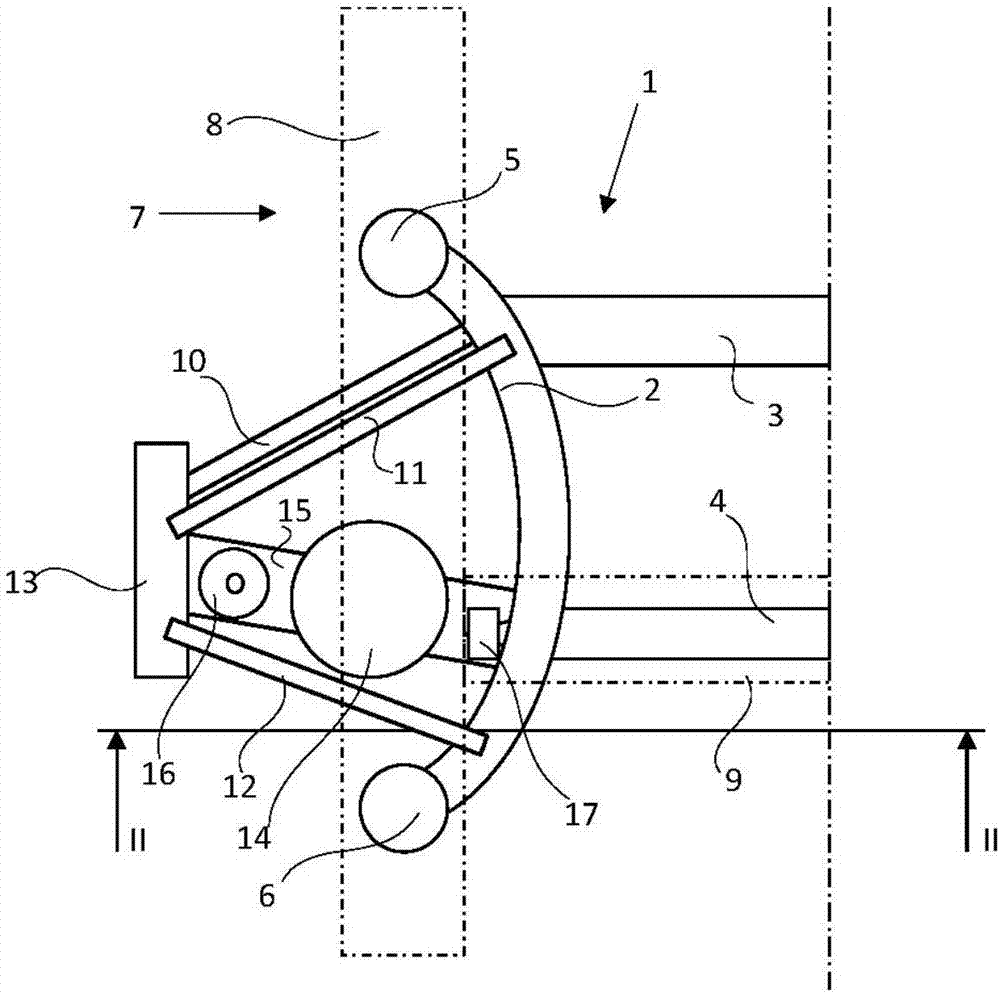
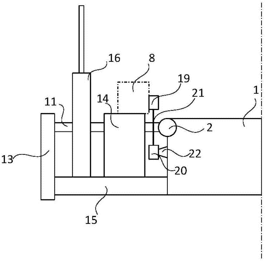
[0021] exist figure 1 with figure 2 shows a schematic and strongly simplified top view and a schematic, strongly simplified rear view, respectively, of a first embodiment of a wheel suspension system according to the invention, wherein the wheel suspension system comprises a longitudinal beam 2 and The subframe 1 of the beams 3, 4, which passes through four subframe supports - two of the four subframe supports 5, 6 are shown - and The body 7 is connected.

[0022] Body 7 is shown schematically by side members 8 and cross members 9 . The longitudinal members 2 of the subframe 1 are connected via a set of control arms 10 , 11 and 12 to a wheel carrier 13 in a manner known per se. The suspension spring 14 of the wheel suspension system is supported on the one hand on the spring control arm 15 on the subframe 1 and on the other hand on the vehicle body 7 . The wheel suspension system also includes a shock absorber 16 which is likewise arranged on the spring control arm 15 and...


PUM


Abstract

A wheel suspension for a motor vehicle with an auxiliary frame 1 connected through auxiliary frame bearings 5, 65 with the vehicle body 7. A support spring 14 is arranged between the vehicle body 7 and a spring link 15 at the auxiliary body, and exerts spring forces on the spring link and thus indirectly on the auxiliary frame. The support spring 14 is arranged near the auxiliary bearings which act in the vehicle direction between the auxiliary frame 1 and the vehicle body 7. Due to the proximity of the auxiliary bearings 17, 23 to the support spring, a part of the spring forces exerted by the support spring 14 is directly guided through the support bearings 17, 23 into the vehicle body 7.

Description

technical field [0001] The invention relates to a wheel suspension system for a motor vehicle. Background technique [0002] A wheel suspension system for a motor vehicle - known for example from DE 19708421 A1 - comprising a subframe together with four subframe supports which connect the subframe to the body and at the same time Decoupled from the excitation caused by the traffic lane. The suspension springs are arranged on the control arm which is simultaneously arranged on the subframe of the wheel suspension system. The subframe support also absorbs the forces in the vehicle height direction in this wheel suspension system, which are generated due to the spring force of the suspension springs on the control arms and thus indirectly on the subframe and contribute to the The subframe supports apply the preload. [0003] For the subframe supports, the design goals are low stiffness in the vehicle x-direction (travel direction), high stiffness in the y-direction (transver...

Claims


Application Information

Patent Timeline
IPC IPC(8): B62D21/00B60G3/00
CPCB60G3/00B62D21/00B60G3/20B60G7/02B60G15/06B60G2200/18B60G2200/184B60G2204/143B60G2204/15B60G2204/41B60G3/18B60G11/00B60G2200/14B60G2204/418B62D21/11
Inventor D·莫洛克
Owner AUDI AG
Learn More