Eureka AIR delivers breakthrough ideas for toughest innovation challenges, trusted by R&D personnel around the world.

Pressure detection device, internal combustion engine equipped with the same, and method for manufacturing the same

a technology of pressure detection device and internal combustion engine, which is applied in the direction of measurement device, rapid change measurement, instruments, etc., can solve the problems of pressure receiver deformation, noise entering the pressure detection device through the case body, and pressure receiver oscillation, so as to minimize the oscillation (fluctuation) of output signals, the effect of reducing noise and minimizing the potential

Active Publication Date: 2018-03-29
CITIZEN FINEDEVICE +2
View PDF4 Cites 2 Cited by
  • Summary
  • Abstract
  • Description
  • Claims
  • Application Information

AI Technical Summary

Benefits of technology

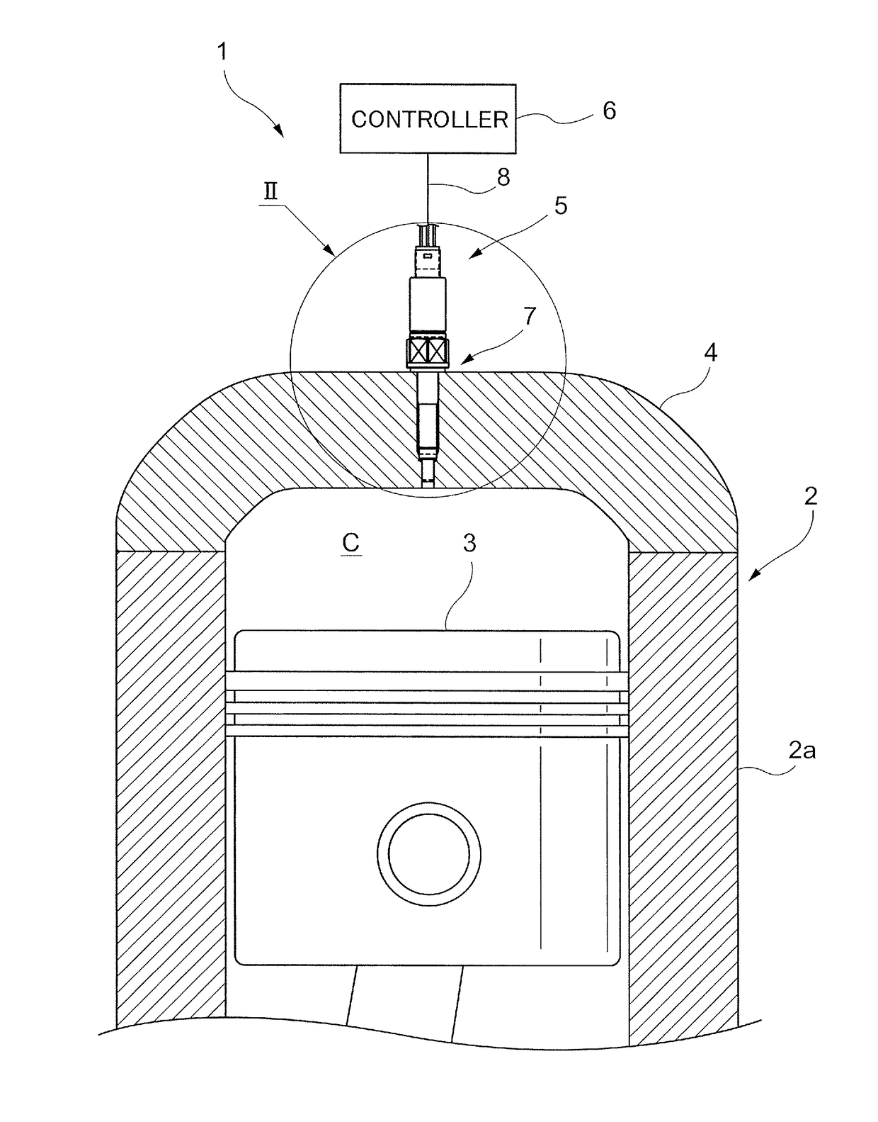
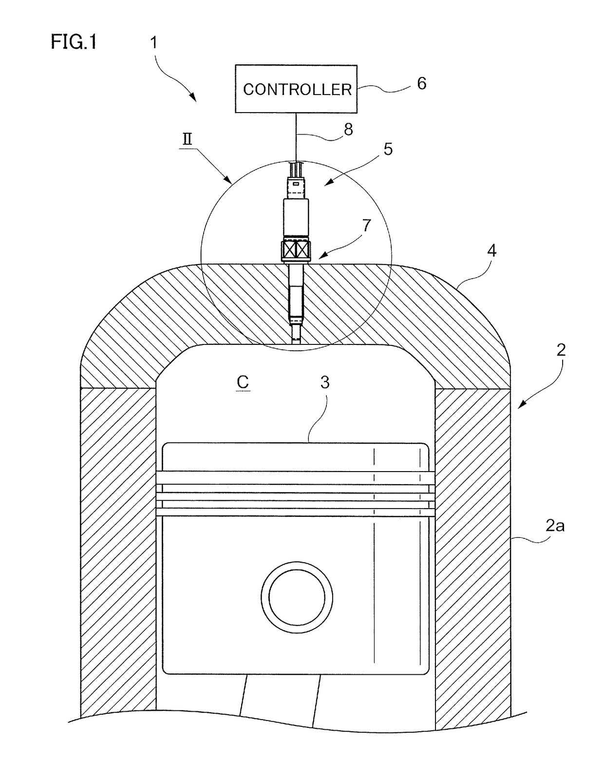
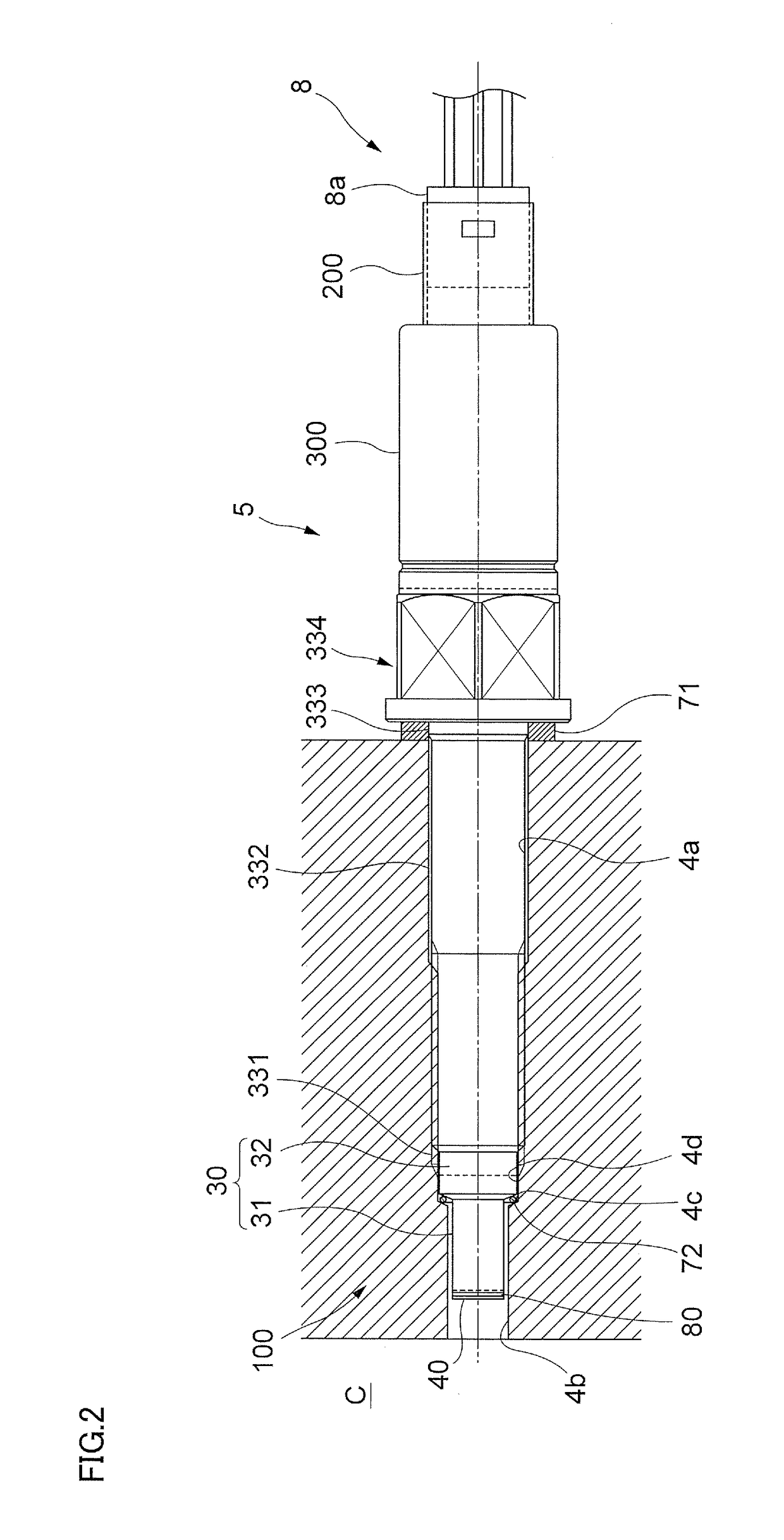
The present invention is related to a pressure detection device for an internal combustion engine. The device is mounted to the cylinder head and is exposed to noise generated outside the engine. To prevent the noise from affecting the device, an insulating layer is applied on the outer surface of the device's housing that faces the inner surface of the communication hole in the cylinder head. This insulating layer also prevents the heat from the combustion gas from affecting the device. Additionally, the diaphragm head of the device is designed to expand and contract with the heat generated during combustion, which ensures consistent performance of the device. The invention is not limited to the specific examples provided and can be modified without changing the main idea.

Problems solved by technology

If the pressure detection device is configured such that the case body (a conductor) electrically connected to the ground of the signal generator is mounted to a mounting body made of a conductor (e.g. the cylinder head) to make the case body electrically continuous with the mounting body, which is then grounded, such a configuration may cause a noise to enter the pressure detection device from the mounting body through the case body.
This noise may cause an error in the pressure that is obtained based on an output from the signal generator.
Also, if the pressure detection device is configured such that the pressure received by the pressure receiver is transmitted to the signal generator, a heat applied to the pressure receiver along with the pressure may cause the pressure receiver to deform due to thermal expansion, and this results in the pressure transmitted from the pressure receiver to the signal generator increasing or decreasing from the original pressure that should be transmitted.
This in turn causes an output value generated by the signal generator to increase or decrease from the proper value that should be output, and as a result the pressure obtained based on the output from the signal generator may contain an error.

Method used


Image

  • Pressure detection device, internal combustion engine equipped with the same, and method for manufacturing the same
  • Pressure detection device, internal combustion engine equipped with the same, and method for manufacturing the same
  • Pressure detection device, internal combustion engine equipped with the same, and method for manufacturing the same

Examples


examples

[0110]Hereinafter, the present invention will be described in more detail using the examples. It should be noted that the present invention is not limited to the following examples; other modifications may be made without departing from the gist of the invention.

[0111]The inventors produced multiple pressure detection devices 5 each with or without the insulating layer 80, whose structure is further differentiated for each pressure detection device 5, provided on the housing unit. The inventors evaluated these pressure detection devices 5 by an antenna irradiation test and a heating simulation test.

[0112]Tables 1 and 2 show the structures of the insulating layers 80 used in the examples (Examples 1-20) and the comparative example, and their evaluation results. Note that the pressure detection device 5 explained in the above exemplary embodiment corresponds to Example 16 shown in Table 2.

TABLE 1ANTENNAFIRSTSECONDTHIRDIRRADIA-INSULATINGINSULATINGINSULATINGTION TESTEXAMPLE / LAYERLAYERLA...


PUM

PropertyMeasurementUnit
inner diameteraaaaaaaaaa
operating temperatureaaaaaaaaaa
thermal conductivityaaaaaaaaaa

Abstract

A pressure detection device includes: a cylindrical body made of a conductor; a pressure receiver made of a conductor, the pressure receiver being mounted to one end side of the body and receiving pressure from the outside; a signal generator arranged inside the body, the signal generator being electrically connected to the pressure receiver and generating a signal corresponding to the pressure received by the pressure receiver; and a cover made of an insulator with a lower thermal conductivity than thermal conductivities of the body and the pressure receiver, the cover continuously covering an outer surface of the pressure receiver and a portion of an outer surface of the body, the portion being located at a side closer to the pressure receiver.

Description

CROSS REFERENCE TO RELATED APPLICATIONS[0001]This application is based on and claims priority under 35 USC § 119 from Japanese Patent Application No. 2016-187827 filed Sep. 27, 2016.BACKGROUNDTechnical Field[0002]The present invention relates to a pressure detection device, an internal combustion engine equipped with the same, and a method for manufacturing the same.Related Art[0003]A pressure detection device that uses a signal generator such as a piezoelectric element has been proposed as a pressure detection device to detect pressure inside a combustion chamber of an internal combustion engine and the like.[0004]Japanese Patent Application Laid-Open Publication No. 2013-156171 discloses a pressure detection device including: a metal cylindrical housing (a case body); a metal diaphragm head (a pressure receiver) mounted to the front end side of the case body to receive pressure from the outside; and a piezoelectric element (a signal generator) arranged inside the case body on the ...

Claims


Application Information

Patent Timeline
Patent Type & Authority Applications(United States)
IPC IPC(8): G01L23/10G01L23/22
CPCG01L23/10G01L23/222
Inventor SATOH, YUSUKETAKAHASHI, KAZUOSUDO, AKISASAKI, KEISUKENAGAI, MASAKATSU
Owner CITIZEN FINEDEVICE
Why Eureka
Eureka Blog
Learn More