Controlling air temperatures of HVAC units

Active Publication Date: 2013-06-13
VIGILENT CORP
View PDF6 Cites 43 Cited by
  • Summary
  • Abstract
  • Description
  • Claims
  • Application Information

AI Technical Summary

Benefits of technology

[0009]Embodiments of the invention are directed to systems, apparatus, and methods of stabilizing environmental maintenance systems with multiple environmental maintenance units (such as HVACs and CRACs) configured to control return air temperature or discharge air temperature. Most units in data centers are configured to be controlled by return air temperature. Units that are controlled by the return air temperature compare the return air temperature to a setpoint. Based on the difference from the s

Problems solved by technology

Effectively, the output of an unit becomes decoupled from its own retu

Method used


Image

  • Controlling air temperatures of HVAC units
  • Controlling air temperatures of HVAC units
  • Controlling air temperatures of HVAC units

Examples


Embodiment Construction

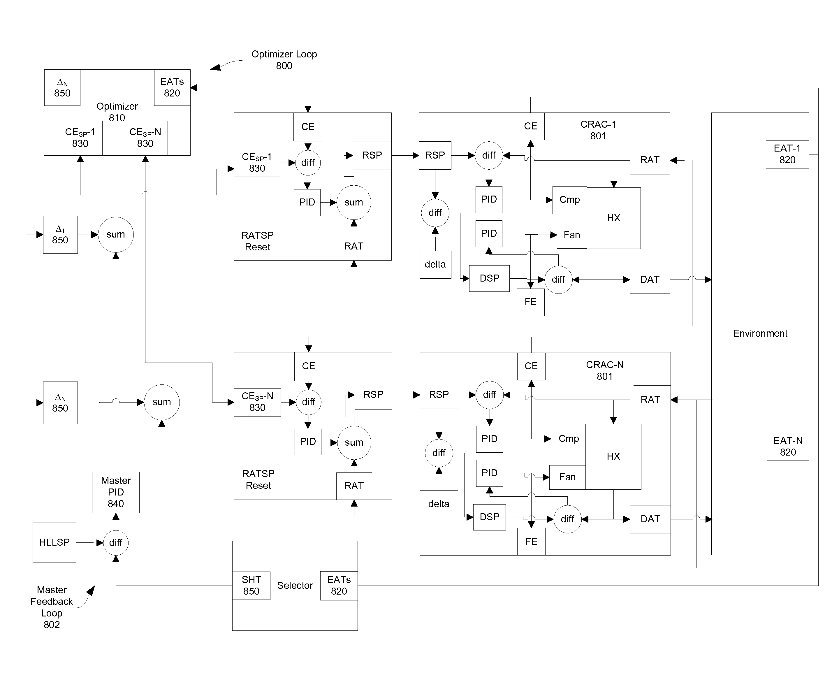
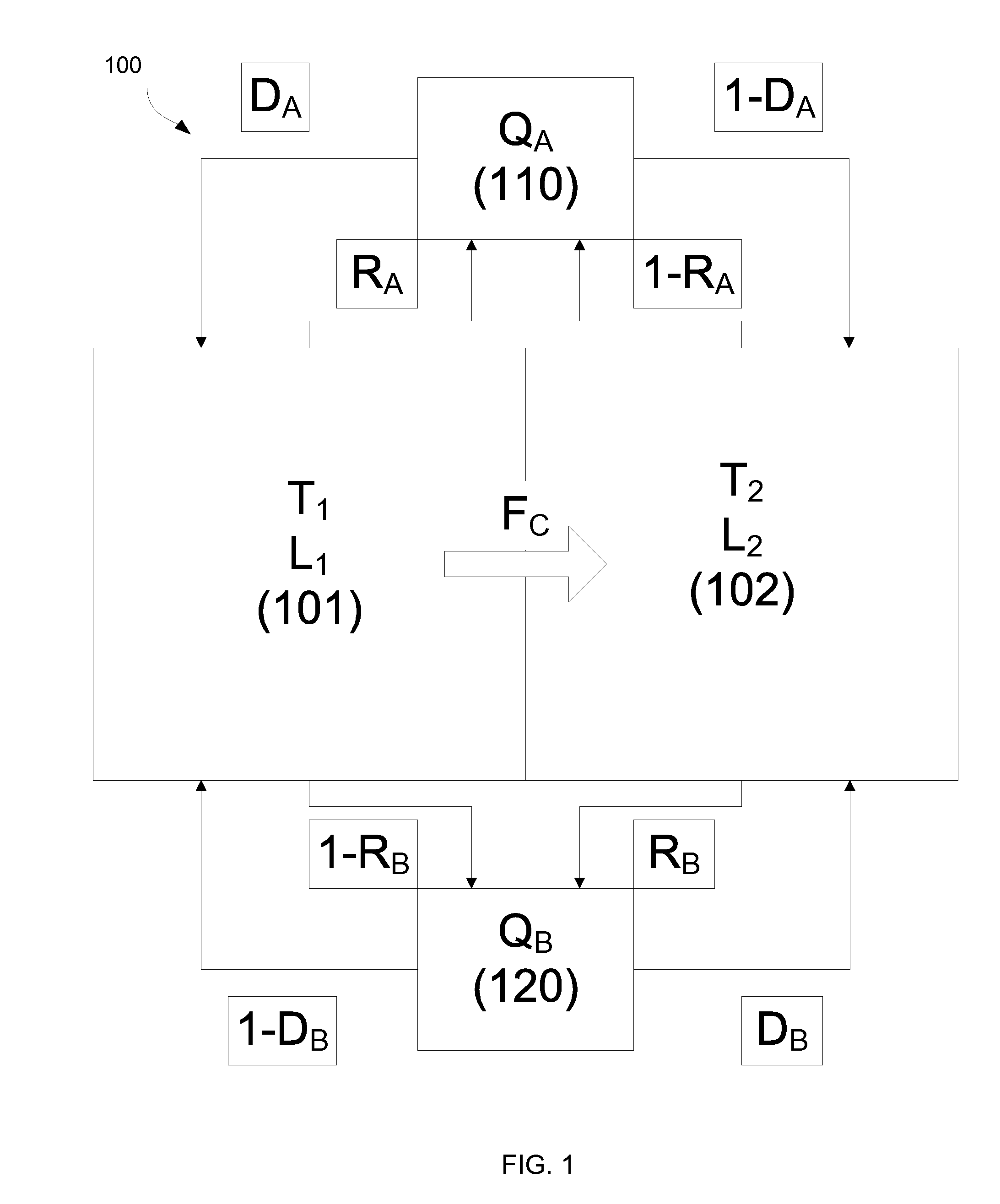
[0026]Embodiments of the invention are directed to systems, apparatus, and methods of stabilizing HVAC systems with multiple HVAC units configured to control return air temperature or discharge air temperature. HVAC units that are controlled by the return air temperature compare the return air temperature to a setpoint. However, in practice, the operation of two or more HVAC units is coupled such that the output of the other HVAC unit can control the return air temperature (or discharge air temperature) of a first HVAC unit. Effectively, the output of an HVAC unit becomes decoupled from its own return air temperature, thereby causing unstable or inefficient operation.

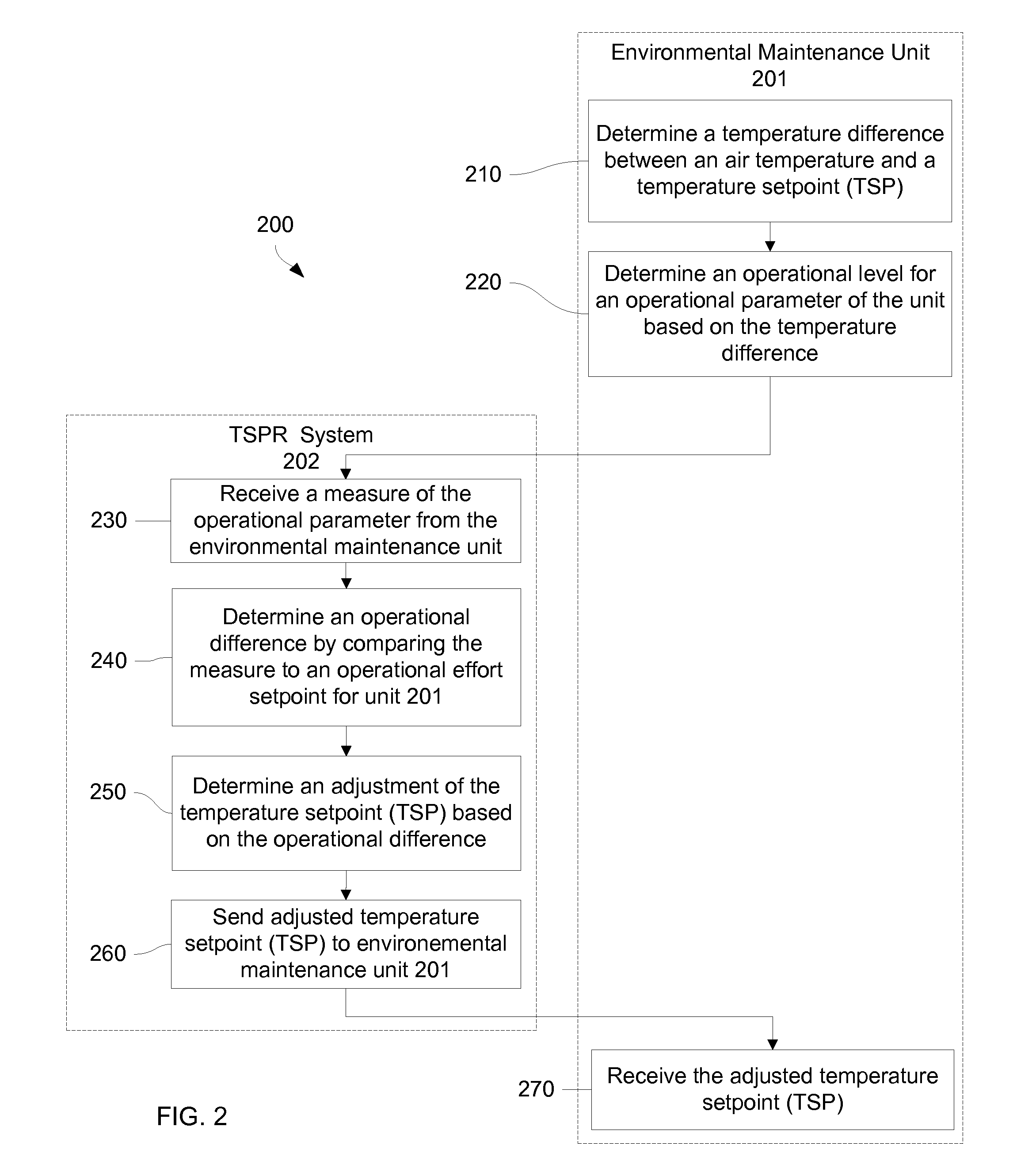
[0027]To address this problem, embodiments can adjust the setpoint of an HVAC unit based on certain criteria (e.g., a desired operational effort of an HVAC unit). A return air or discharge air temperature setpoint reset (TSPR) system can be included in each HVAC unit. The TSPR resets the temperature setpoint (TSP) of th...


PUM


Abstract

Systems and methods of stabilizing HVAC systems with multiple HVAC units configured to control return air temperature or discharge air temperature are provided. HVAC units that are controlled by the return air temperature compare the return air temperature to a setpoint that determines whether the HVAC unit's operation increases, decreases, or stays the same. By adjusting the setpoint of an HVAC unit based on certain criteria (e.g., a desired operational effort of an HVAC unit) the system can be stabilized. A temperature setpoint reset (TSPR) system can be included in each HVAC unit that resets the temperature setpoint (TSP) of the HVAC unit so that the HVAC unit operates within a desired operational effort (e.g. compressor speed or valve position). A master feedback loop and optimizer loop may be implemented to further control the behavior of the HVAC system.

Description

CROSS-REFERENCES TO RELATED APPLICATIONS[0001]The present application claims priority from and is a nonprovisional application of U.S. Provisional Application No. 61 / 569,728, entitled “CONTROLLING AIR TEMPERATURES OF HVAC UNITS” filed Dec. 12, 2011, the entire contents of which are herein incorporated by reference for all purposes.[0002]The present application is related to commonly owned U.S. application Ser. No. 13 / 215,189, entitled “ENERGY-OPTIMAL CONTROL DECISIONS FOR HVAC SYSTEMS,” filed Aug. 22, 2011 and U.S. application Ser. No. 12 / 396,944, entitled “METHOD AND APPARATUS FOR COORDINATING THE CONTROL OF HVAC UNITS,” filed Mar. 3, 2009, the disclosure of which is incorporated by reference in its entirety. the disclosure of which is incorporated by reference in its entirety.BACKGROUND[0003]The present invention generally relates to environmental control systems, such as heating, ventilation, and air conditioning (HVAC) systems, which can be used to control the temperature and / or...

Claims


Application Information

Patent Timeline
IPC IPC(8): F24F11/00
CPCF24F11/00F24F11/0012G05D23/1934Y02B30/746F24F11/0079F24F11/30F24F11/77F24F2110/10Y02B30/70F24F11/58F24F11/76F24F11/46F24F11/63F24F11/86
Inventor FEDERSPIEL, CLIFFORD C.
Owner VIGILENT CORP
Why Eureka
Try Eureka