
Clamping force generator

a generator and clamping technology, applied in the direction of friction gearings, gearing elements, friction gearings, etc., can solve the problems of difficulty in determining the proper clamping force generator for any given application, and difficulty in providing the adequate pre-load (or initial clamping force) necessary

Active Publication Date: 2013-06-20
FALLBROOK INTPROP COMPANY
View PDF4 Cites 50 Cited by
  • Summary
  • Abstract
  • Description
  • Claims
  • Application Information

AI Technical Summary

Benefits of technology

The patent text describes devices and methods for generating clamping force in mechanical power transmissions, particularly in continuously variable transmissions. The technical effects of the patent include providing adequate clamping force for various operating conditions of the transmissions and addressing difficulties in providing the initial clamping force to avoid total traction loss and inefficiencies. The devices and methods disclosed herein provide solutions to these needs in the relevant technology.

Problems solved by technology

However, devising the proper clamping force generator for any given application can be challenging.
For example, difficulties can arise in providing the adequate pre-load (or initial clamping force) necessary to avoid total traction loss and / or inefficiencies (due to lost motion, for example).

Method used


Image

  • Clamping force generator
  • Clamping force generator
  • Clamping force generator

Examples


Embodiment Construction

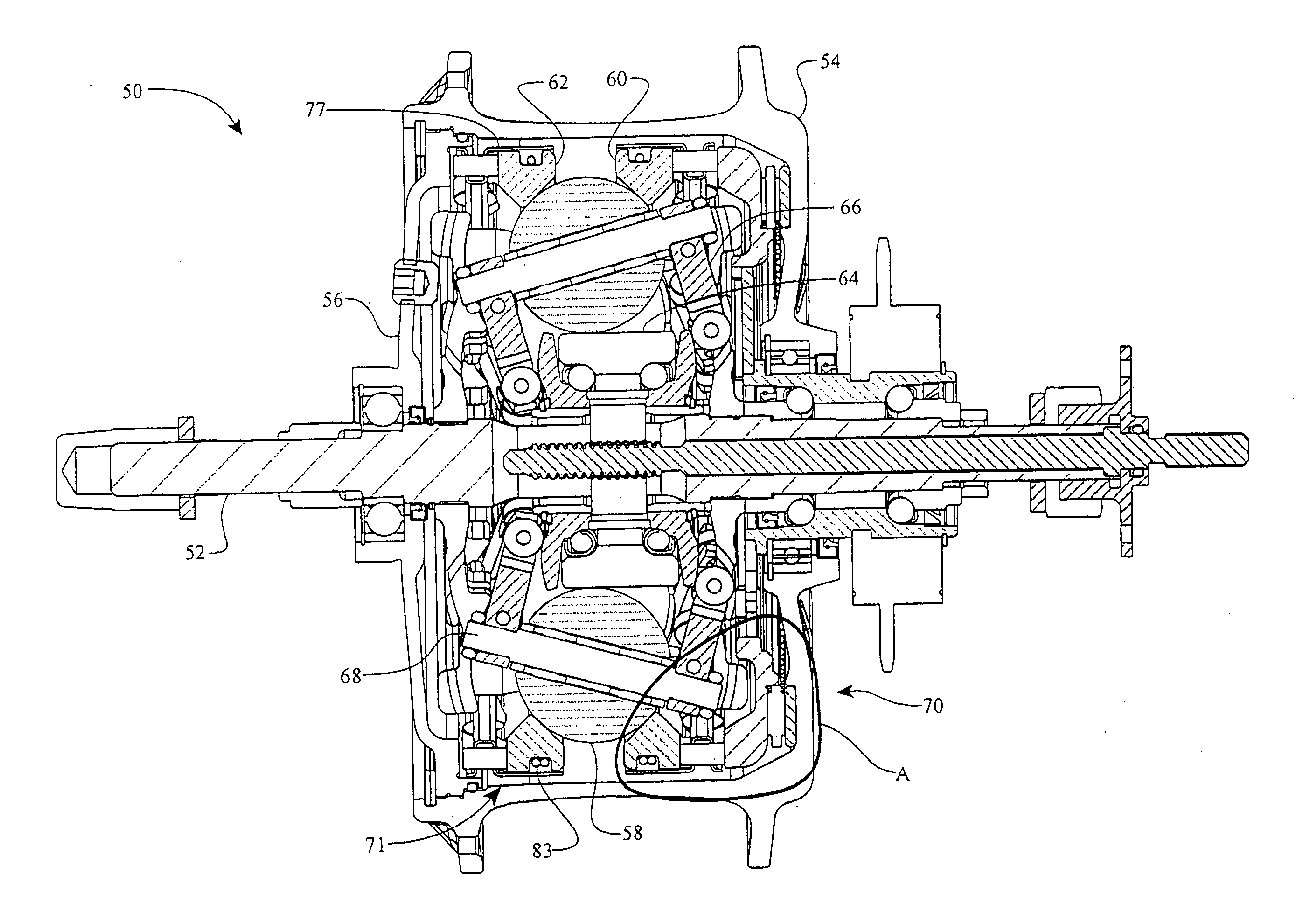
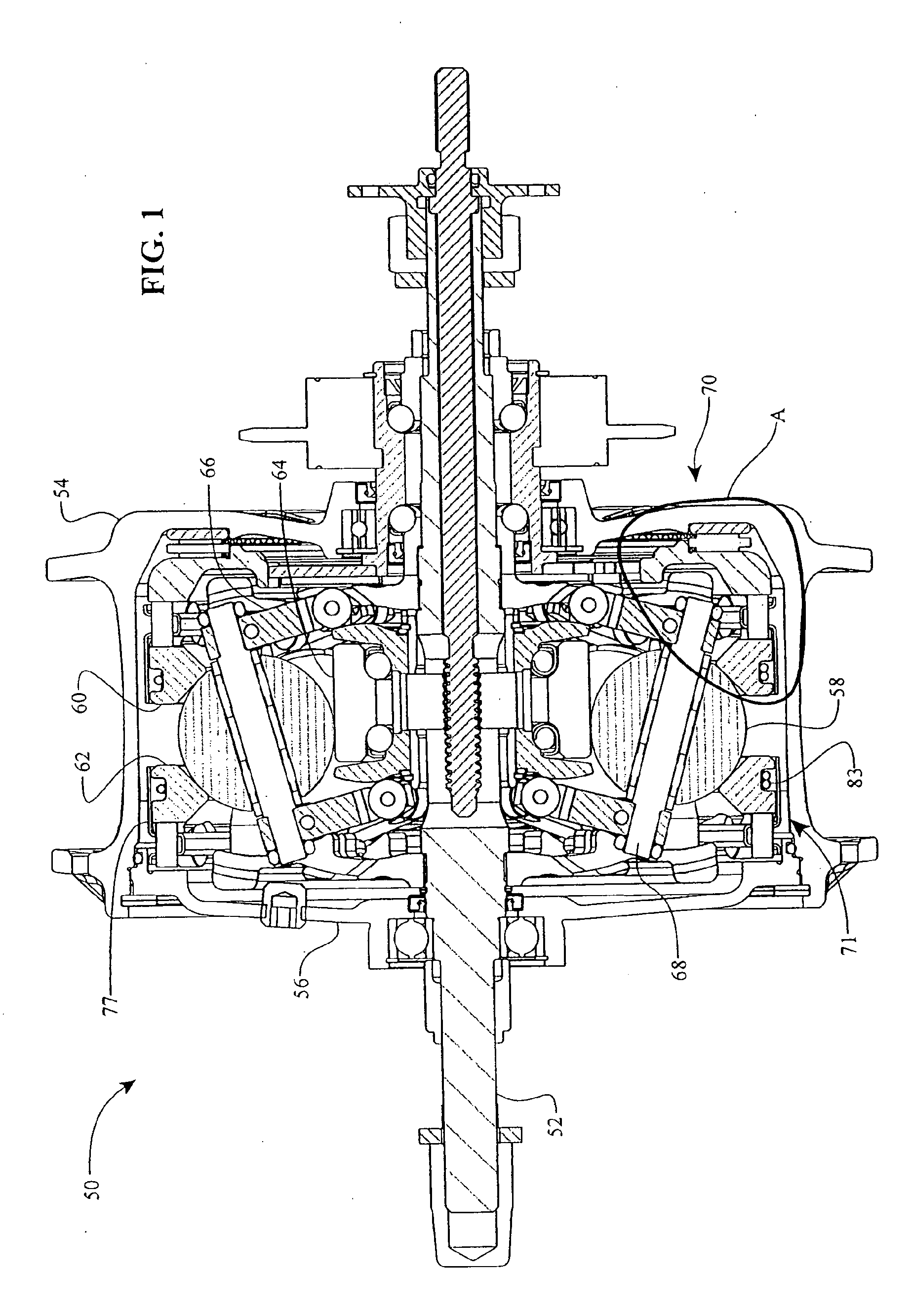
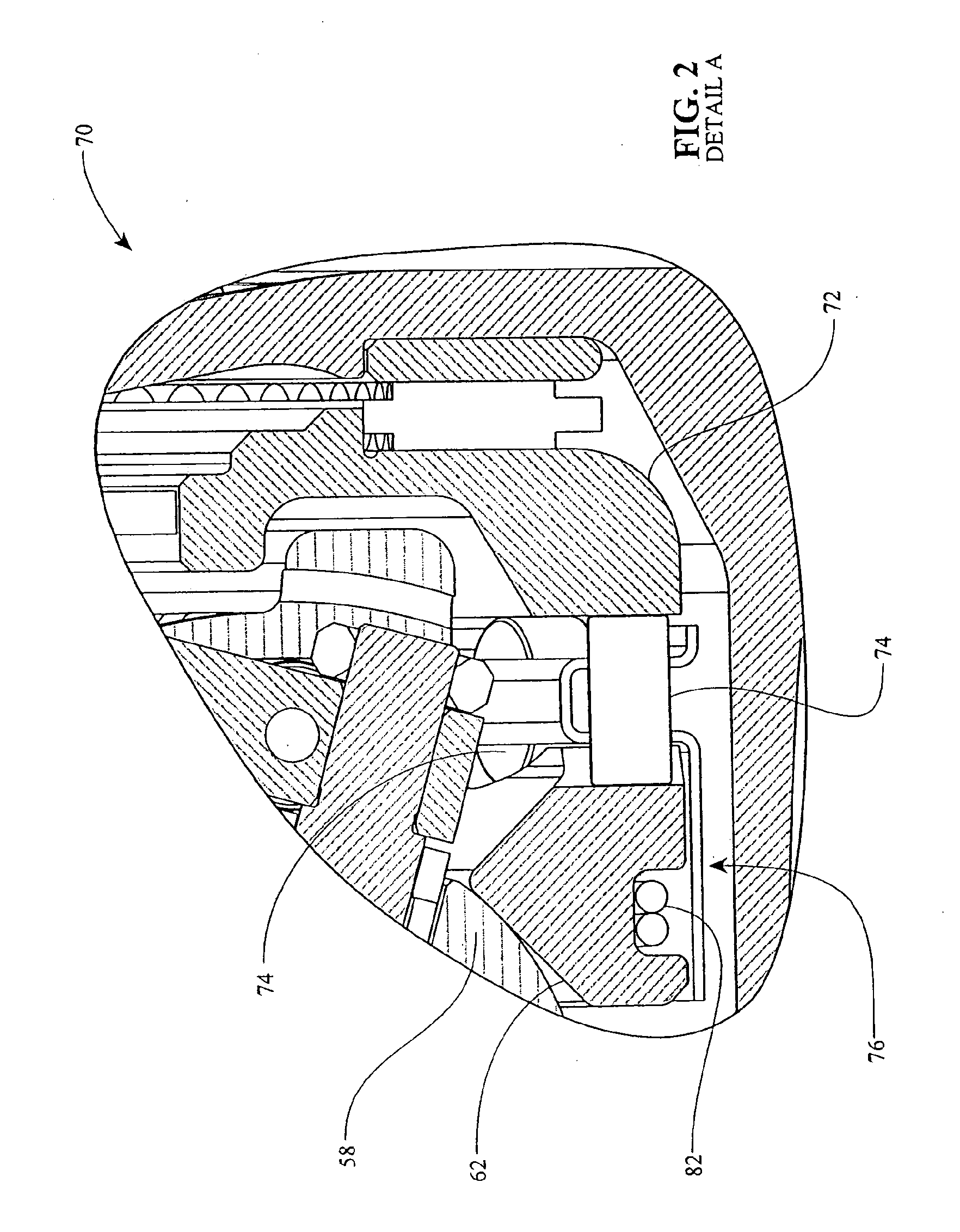
[0042]The preferred embodiments will now be described with reference to the accompanying figures, wherein like numerals refer to like elements throughout. The terminology used in the description presented herein is not intended to be interpreted in any limited or restrictive manner simply because it is being utilized in conjunction with a detailed description of certain specific embodiments of the invention. Furthermore, embodiments of the invention may include several novel features, no single one of which is solely responsible for its desirable attributes or which is essential to practicing the inventions herein described. Embodiments of the clamping force generators described here can be suitably adapted to continuously variable transmissions of the type disclosed in U.S. Pat. Nos. 6,241,636; 6,419,608; 6,689,012; and 7,011,600. The entire disclosure of each of these patents is hereby incorporated herein by reference.

[0043]As used here, the terms “operationally connected,”“operat...


PUM


Abstract

Mechanisms and methods for clamping force generation are disclosed. In one embodiment, a clamping force generator includes a spring coupled to a traction ring and to a load cam roller cage. The traction ring can be provided with a recess to receive the spring. In some embodiments, a relatively short spring is provided. In other embodiments, a spring couples to a wire and the spring-wire combination couples to the traction ring and the load cam roller cage. In some embodiments, the load cam roller cage is provided with tabs adapted to engage the wire and / or the spring. In yet other embodiments, the traction ring is configured to receive a dowel pin for coupling to the spring. One or more of the tabs can include a tab notch that cooperates with a stop pin coupled to the traction ring to provide adjustment of the travel of the load cam roller cage.

Description

RELATED APPLICATIONS[0001]This application is a continuation of U.S. patent application Ser. No. 12 / 514,062, filed May 7, 2009, which is a national phase application of Application No. PCT / US2007 / 023315, filed Nov. 6, 2007, which claims the benefit of U.S. Provisional Application No. 60 / 864,941, filed Nov. 8, 2006. The disclosures of all of the above-referenced prior applications, publications, and patents are considered part of the disclosure of this application, and are incorporated by reference herein in their entirety.BACKGROUND OF THE INVENTION[0002]1. Field of the Invention[0003]The field of the invention relates generally to mechanical power transmissions, and more particularly the invention pertains to devices and methods relating to generating clamping force in certain types of said transmissions.[0004]2. Description of the Related Art[0005]Certain transmissions, for example some continuously or infinitely variable transmissions, often include one or more mechanisms for gen...

Claims


Application Information

Patent Timeline
Patent Type & Authority Applications(United States)
IPC IPC(8): F16H61/664
CPCF16H15/28F16H15/52Y10T74/18304F16H61/664Y10T74/18312F16H25/186
Inventor POHL, BRAD P.DAWE, DANIEL J.LOHR, CHARLES B.NICHOLS, JON M.
Owner FALLBROOK INTPROP COMPANY
Learn More